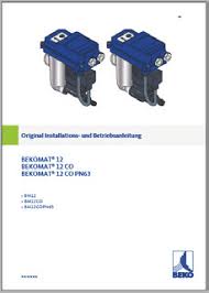
 BEKOMAT® 12 BEKOMAT® 12 CO BEKOMAT® 12 CO PN63
BEKO TECHNOLOGIES GmbH in the manual. • Adhere to the prescribed maintenance Inappropriate cleaning and the use of the wrong cleaning media may result in ...
 Refrig. Dryers - ACT Dryer Price Listl
Bekomat No-Air-Loss drain. • Models ACT20U to ACT75U also available in 230/1/60 power supply. Consult CAG Purification for pricing and delivery. ... Hot gas by- ...
 2910303200 INLET VALVE KIT 2910303200 2910303600 MIN
6221337300 ELECTROV.DE PURGE P/BEKOMAT 12. 6221337300. 6221337900 AGENT 6224425800 CALE MOTEUR 30 KW RLR 40 A 75M. 6224425800. 6224425900 TUBE ACIER D.EXT 12 ...
 Introduction
17 мая 2004 г. 12 Auto cleaning. Autocleaning available. 13 Auto cleaning sampling ... BEKOMAT 12 condensate drain. The choice between both systems depends ...
 for the World Market 2012
evant processes for exhaust air purification. The most important membrane types for drive outputs of 75 kW to 250 kW and a maximum operating pressure of.
 Pumps and Compressors for the World Market 2009
capacity up to 12 m3/min. With ratings of 0.4 kW up to 110 kW. Tsurumi pumps are extremely rugged low on maintenance and have no problem with dry running
 PRODUCTS REMOVED FROM THE ETPL PRIOR TO 1 APRIL 2010
1 апр. 2012 г. ... 12. 22-Sep-05. Boiler Equipment. Heat Recovery from Condensate and Boil. TC Fluid ... kW 4P. 01-Mar-10. Motors & Drives. Single Speed Induction ...
 STORK INDUSTRIAL STOCK LIST WWW.STORKINDUSTRIAL.COM
Bekomat 12 230Vac KA12A10A0 2000018 Condensate Drain. Bekomat 12 CO PN6312 Lovejoy LJ L050 HUB 12MM 4X1.8MM KW (JW500008) Coupling. Lovejoy LS099/100 ...
 VQ Mining
TAG MOTOR: 8511A 12 KW
 BEKOMAT® 12 KW
Vous venez d'acquérir un purgeur de condensat BEKOMAT et nous vous en félicitons. The moisture indicator BEKOMAT 12 KW ... 17 Cage serre-câble.
 BEKOMAT 12 KW Moisture Indicator
The BEKOMAT 12 KW moisture indicator has been developed especially for dealing with difficult points and situations in your compressed-air network.
 BEKOMAT®
ball valve. $15344. * per year loss at 8
 VS COVE
To maximize the Energy Savings the Purestream ACT VS range is equipped with an electronic Zero Loss Drain. Bekomat Zero-loss Drain. DMC 50 CONTROLLER. The
 Equipements dateliers et outils 2016/2017
(1 set = 4 pièces + 12 inserts en plastique). LG. Dispositif d'aide au montage (presse-talon). B est Product by Derendinger. TOPSELLER
 Introduction
17 mai 2004 12. 1.1.3 INGOLD PORTS AND HOUSINGS FOR SENSOR FITTING ... Figure 14: General concept of the liquid loop with filtration module.
 Compressed Air Compendium
3 févr. 2010 12. Fundamentals of compressed air. Norm volume flow V ... single stage compression a maximum 20 kW motor rating ... 10 Bekomats.
 Pumps and Compressors for the World Market 2009
page 12. Research done on side-channel pump stages of a booster vacuum 55 kW motor is supplied with an impeller ... High pressure cleaning systems.
 ??????????????????????????PLC
HOYER HOYER HMA2-132S-4 5.5KW/11A. REXROTH R900589988 elco NI40-C40-OP6L-Q12. HYFRA SVK540/1SONDER;171957. ORION 5.10E+07. Jabsco 52200-2011.
 www.elmag.at
The 12/24 volt series are special compressors for mobile applications or for High-performance oil/air coolers perfect air filtration and cooling ...
Otto-Boge-Str. 1-7
D-33739 Bielefeld
info@boge.com www.boge.comCompendium online: www.drucklufttechnik.de
Revised 6th edition 2004
The existing publication has been carefully developped. However, author and publisher do not assume liability for the correctness of statements, notes and advice as well no t for eventual errata.All rights reserved.
Reproduction, including that of excerpts, is forbidden. No part of this publication may be reproduced in any way (photocopy, mi crofilm or any other medium) or be used, copied or distributed on electronic systems, educational pur poses included, without the prior written consent of the publisher.© 2004. All rights reserved by BOGE.
Published by BOGE, Otto-Boge-Str. 1-7, D-33739 BielefeldAuthor of editions 1-5: Ulrich Bierbaum (BOGE)
6th edition revised by Jürgen Hütter (BOGE)
Printed on woodfree paper with mineralfree colours Distribution: Hoppenstedt Bonnier Zeitschriften GmbH,D-64295 Darmstadt
Print: Druckhaus Darmstadt GmbH,
D-64295 Darmstadt
Pr inted in GermanyISBN: 3-935772-12-2
ITable of contents
Contents
1.1 The history of compressed air...............................................1
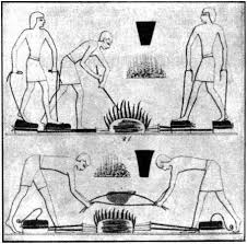
1.1.1 The origin of compressed air................................................1
1.1.2 The first applications of compressed air...............................2
1.2 Units and formula symbols....................................................6
1.2.1 Basic units........................................................................
....61.2.2 Compressed air units ...........................................................6
1.3 What is compressed air ?.......................................................7
1.3.1 The composition of air..........................................................7
1.3.2 The properties of compressed air ........................................7
1.3.3 How does compressed air behave? .....................................7
1.4 Physical fundamentals...........................................................8
1.4.1 Temperature ........................................................................
.91.4.2 Volume ........................................................................
.........91.4.3 Pressure........................................................................
.....101.4.4 Volume flow ........................................................................
111.5 Compressed air in motion....................................................13
1.5.1 Flow behaviour ...................................................................13
1.5.2 Types of flow ......................................................................13
2.1 The advantages of compressed air.....................................14
2.2 Pressure ranges....................................................................17
2.3 Possible applications for compressed air...........................18
2.3.1 Tensioning and clamping with compressed air...................18
2.3.2 Conveyance by compressed air.........................................18
2.3.3 Pneumatic drive systems...................................................19
2.3.4 Spraying with compressed air............................................19
2.3.5 Blowing and flushing with compressed air..........................19
2.3.6 Testing and inspection with compressed air .......................20
2.3.7 Using compressed air for process control..........................20
2.4 Examples of specialised applications.................................21
3.1 Compressors (compactors)..................................................24
3.1.1 Dynamic compressors ( Turbo-compressors ) ....................24
3.1.2 Displacement compressors................................................24
3.2 Types of compressor............................................................25
3.2.1 Standard compressors .......................................................26
3.2.2 Piston (reciprocating) compressor......................................27
3.2.3 Diaphragm compressor ......................................................29
3.2.4 Free piston compressor......................................................30
3.2.5 Rotary vane compressor....................................................31
3.2.6 Liquid ring compressor.......................................................32
3.2.7 Screw compressor .............................................................33
3.2.8 Roots compressor..............................................................34
3.2.9 Axial compressor................................................................35
3.2.10 Radial compressor.............................................................36
Part 1
Fundamentals of
compressed airPart 2
Applications for
pneumaticsPart 3
Compressed air
generatorsChapter Page IITable of contents
Part 4
Control of compressorsChapter Page
3.3 Piston compressors..............................................................37
3.3.1 General........................................................................
......373.3.2 Suction capacity - output....................................................38
3.3.3 Cooling........................................................................
.......393.3.4 Coolant........................................................................
.......403.3.5 Control of reciprocating piston compressors......................40
3.3.6 Advantages of reciprocating piston compressors...............40
3.3.7 Components of a piston compressor..................................41
3.4 Screw compressors..............................................................42
3.4.1 General........................................................................
......423.4.2 Compression process ........................................................42
3.4.3 Method of operation ...........................................................43
3.4.4 Oil circuit........................................................................
....443.4.5 Pneumatic circuit................................................................45
3.4.6 Heat reclamation................................................................46
3.4.7 Intake control......................................................................46
3.4.8 Advantages of screw compressors.....................................46
3.4.9 Main components of a screw compressor..........................47
3.5 Components........................................................................
..483.5.1 Drive motor........................................................................
.483.5.2 Drive belts ........................................................................
..483.5.3 Belt tensioning....................................................................48
3.5.4 Inlet and pressure valves...................................................49
3.5.5 Safety valve........................................................................
493.5.6 Intake filter........................................................................
..493.6 Compressor lubricants and coolants..................................50
4.1 Pressure definitions..............................................................51
4.2 Operating status....................................................................52
4.2.1 Stopped ( L
0 ) .....................................................................524.2.2 Idle ( L
1 .....524.2.3 Part-load ........................................................................
....534.2.4 Operating load ( L
2 ) ..........................................................534.3 Controlling individual compressors....................................54
4.3.1 Intermittent control .............................................................54
4.3.2 Idle mode control................................................................54
4.3.3 Delayed intermittent control................................................55
4.3.4 Part-load control.................................................................56
4.3.4.1 Proportional regulation.......................................................56
4.3.4.2 Frequency control...............................................................57
4.4. The ARS control concept.....................................................59
4.4.1 Autotronic........................................................................
...604.4.2 Ratiotronic........................................................................
..604.4.3 Supertronic........................................................................
.61 IIITable of contents
Part 5
Compressed air treatmentChapter Page
4.5 Control of several compressors..........................................62
4.5.1 MCS 1 and MCS 2 .............................................................62
4.5.2 MCS 3........................................................................
........634.5.3 MCS 4........................................................................
........644.5.4 MCS 5........................................................................
........654.5.5 MCS 6........................................................................
........664.5.6 MCS 7........................................................................
........675.1 Why treatment ?....................................................................68
5.1.2 Planning information ..........................................................69
5.1.3 Consequences of poor treatment .......................................70
5.1.3 Impurities in the air.............................................................71
5.2 Water in the compressed air................................................72
5.2.1 Atmospheric humidity.........................................................72
5.2.2 Dew points ........................................................................
.735.2.3 Air moisture content ...........................................................73
5.2.4 Quantity of condensate during compression......................74
5.2.5 Example for calculating quantities of condensate..............75
5.2.6 Quantity of condensate on a humid Summer day ..............76
5.2.7 Determining the pressure dew point...................................77
5.2.8 Pressure dew point after removal of pressure ....................78
5.3 Compressed air quality.........................................................79
5.3.1 Quality classes defined in DIN ISO 8573-1.......................79
5.4 Methods of drying.................................................................80
5.4.1 Operating conditions..........................................................81
5.4.2 Condensation by high pressure..........................................82
5.4.3 Condensation by refrigeration drying.................................83
5.4.4 Diffusion by membrane drying............................................84
5.4.5 Sorption by Absorption.......................................................85
5.4.6 Sorption by Adsorption.......................................................86
5.4.6.1 Heatless regeneration ........................................................87
5.4.6.2 Internal heat regeneration..................................................88
5.4.6.3 External heat regeneration.................................................89
5.4.6.4 Vacuum regeneration .........................................................90
5.4.7 Arrangement of the refrigeration compressed air dryer......91
5.4.7.1 Dryer before the compressed air receiver ..........................91
5.4.7.2 Dryer behind the compressed air receiver..........................92
5.5 Compressed air filters..........................................................93
5.5.1 Basic terminology of filters.................................................93
5.5.1.1 Filter separation rate Δ [ % ] ...............................................93
5.5.1.2 Pressure drop p ...............................................................94
5.5.1.3 Operating pressure ............................................................94
5.5.2 Dust separators..................................................................95
5.5.3 Pre-filters........................................................................
....965.5.4 Microfilters........................................................................
..965.5.5 Active carbon filters ............................................................99
5.5.6 Active carbon adsorbers...................................................100
5.5.7 Sterile filters .....................................................................101
IVTable of contents
Part 7
Compressed air
requirementPart 6Disposal of condensate
Part 8
Determining the size of
the compressor stationChapter Page6.1 Condensate........................................................................
..1026.2 Condensate drains..............................................................103
6.2.1 Condensate drains with manual valves ............................104
6.2.2 Condensate drains with float control................................104
6.2.3 Condensate drains with timer operated solenoid valves...105
6.2.4 Condensate drains with electronic level control................106
6.2.5 Condensate drains with float operated level control .........107
6.3 Condensate treatment........................................................108
6.3.1 Oil-water separators .........................................................109
7.1 Consumption of compressed air by pneumatic devices.110
7.1.1 Consumption of nozzles...................................................110
7.1.1.1 Compressed air consumption of cylindrical nozzles.........111
7.1.1.2 Compressed air consumption of paint spray guns ...........112
7.1.1.3 Compressed air consumption of jet nozzles.....................113
7.1.2 Compressed air consumption of cylinders .......................114
7.1.3 Compressed air consumption of tools..............................115
7.2 Determining compressed air requirement........................117
7.2.1 Average operation time....................................................117
7.2.2 Simultanity factor..............................................................118
7.2.3 Defining compressed air requirement ..............................119
7.2.3.1 Automatic consumer devices............................................119
7.2.3.2 General consumer devices...............................................120
7.2.3.3 Total compressed air consumption...................................120
7.2.4 Allowances for losses and reserves .................................121
7.2.5 FAD Required L
B7.3 Compressed air loss...........................................................122
7.3.1 Costs of compressed air loss...........................................122
7.3.2 Quantifying leakage.........................................................123
7.3.2.1 Quantifying leakage by emptying the receiver..................123
7.3.2.2 Quantifying leakage by measuring working time ..............124
7.3.3 Limits for leakage .............................................................125
7.3.4 Measures for minimising compressed air loss..................125
7.3.5 Reconstructing a pneumatic network ...............................126
8.1 The type of compressor......................................................127
8.1.1 Screw compressors..........................................................127
8.1.2 Piston compressors..........................................................127
8.2 Maximum pressure P
max8.2.1 Factors influencing cutout pressure P
max .........................1288.3 Determining the volume of a compressed air receiver...129
8.3.1 Recommendations for the volume of compressed air
quotesdbs_dbs25.pdfusesText_31[PDF] BEL AIR - Pam Golding Properties
[PDF] bel air loisirs - belair moto
[PDF] Bel Air März 2016
[PDF] Bel appart atypique aux pieds des pistes, refait à neuf... WIFI
[PDF] Bel appartement à vendre St laurent Du Var
[PDF] bel appartement de 5 pièces au 3ème étage descriptif conditions - Anciens Et Réunions
[PDF] Bel appartement de deux chambres à Cala de Bou à vendre
[PDF] Bel appartement en excellent quartier de la Havane
[PDF] Bel appartement rénové de 86 m2
[PDF] Bel appartement T4
[PDF] Bel Automne - Rue de la Sanglerie, 44480 LES
[PDF] Bel et grand appartement de type 3 au 1er étage avec garage
[PDF] BEL ETE SUR LE SITE DE MONCO
[PDF] Bel Hôtel 35 chambres à Lourdes

