 FANUC Robot ARC Mate 120iC M-20iA MECHANICAL UNIT
CONNECTION of controller maintenance manual for details. Emergency stop board or Panel boa rd. Fig.3.1 Connection diagram for external emergency stop button
 FANUC Robot series R-30iB Mate + Mate Plus Maintenance Manual
FANUC Robot M-20iB/25. M-20iB/25. M-20iB. Medium. FANUC Robot ARC Mate 50iD. ARC Fig.B(z) RI/RO connection diagram (M-2iA M-3iA). (There are many type EE ...
 FANUC ROBOT M-20iB MECHANICAL UNIT MAINTENANCE
The descriptions and specifications contained in this manual were in effect at the time this manual was approved for printing. FANUC America Corporation.
 FANUC Robot series
2 Before replacing components read the maintenance manual to understand the A (j) Motor power connection (M-1iA/0.5S(4-Axis)). Page 247. A.TOTAL CONNECTION ...
 OPERATION AND MAINTENANCE HANDBOOK
Page 1. FANUC Series 16*/160*/160*s-MODEL B. FANUC Series 18*/180*/180*s-MODEL manual return to the reference position (0)/not checked (1). #7 BFA : When a ...
 FANUC Robot M-20iB
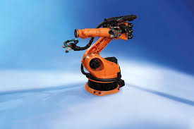
M-20+B. Middle Size Intelligent Handling Robot. FEATURES. FANUC Robot M-20iB is a middle size handling robot with 25 to 35kg payload capacity. ○ Three models
 FANUC Robot series R-30iA/R-30iA Mate/R-30iB CONTROLLER
Refer to controller maintenance manual for details. Emergency stop board or Panel board. (Note). In case of R-30iB. Terminals EAS1
 Seventh Axis EN
FANUC. M-20iA; M-20iA/20M; ARC Mate 120C; M-20iB/25; M-20iB/25C; M-20iA/35M. 20-25 210-250. KAWASAKI RS020N; RS010L. 10-20. 230. KUKA. KR CYBERTECH / KR
 Robotic equipment
Locking clip for manual opening for SH system holder as well as R-Tec Box ... Fanuc M-20iB/25. Fanuc M-20iA/35M. Fanuc M-20iA/35MT. Fanuc M-900iA 260L. Fanuc ...
 FANUC Robot ARC Mate 120iC M-20iA MECHANICAL UNIT
Before using the Robot be sure to read the "FANUC Robot Safety Manual (B-80687EN)" and CONNECTION of controller maintenance manual for details.
 FANUC Robot series R-30iB Mate + Mate Plus Maintenance Manual
The descriptions and specifications contained in this manual were in effect at the M-20iA/35M. FANUC Robot M-20iB/25. M-20iB/25. M-20iB.
 FANUC ROBOT M-20iB MECHANICAL UNIT MAINTENANCE
The descriptions and specifications contained in this manual were in effect at the time this manual was approved for printing. FANUC America Corporation.
 FANUC Robot series
FANUC Robot series. RIA R15.06-1999 COMPLIANT. R-30iA Mate CONTROLLER. MAINTENANCE MANUAL. MARMTCNTR06071E REV. F. This publication contains proprietary
 FANUC Robot LR Mate 200iD ARC Mate 50iD MECHANICAL UNIT
Then press F4 MANUAL. ROBOT MAINTENANCE. 1/10. Setup Robot System Variables. Group Robot Library/Option Ext Axes. 1 LR
 DIY Robotics
The robotic cell is equipped with a FANUC M-10iD/12 M-20iB/25 or For maintenance on the robot
 Automation Control for Powertrain Applications - Rockwell
Rockwell Automation and FANUC: CNC Robot
 FANUC Robot Vision and Force Control
Vision sensor and force sensor with the FANUC robots realize M-1iA M-3iA
 Linear Shaft Motor Install Users Guide
procedures required for installation operation
 Etunimi Sukunimi
Opinnäytetyön toimeksiantajana sekä kustantajana toimi JTA Connection. Opinnäyte- Robotin käsivarsi Fanuc M-20iB/25 (Fanuc robots. M-20iB-25.).
USER MANUAL
SATELLITE
CELLSAUGUST 2019
Page 2 of 18
TABLE OF CONTENT
SECURITY AND RISK MANAGEMENT ..................................................................................................... 3
1. ................................................................................................................... 3
2. Security components .......................................................................................................................... 3
a) Emergency stop buttons ................................................................................................................ 3
b) Sheet metal panels and polycarbonate ......................................................................................... 3
c) Emergency exit security handles ................................................................................................... 4
3. Lockout procedure .............................................................................................................................. 4
ROBOTIC CELL COMPONENTS .............................................................................................................. 6
1. Robotic cell description ....................................................................................................................... 6
2. FANUC Robot ....................................................................................................................................... 6
3. Lockable side doors ............................................................................................................................ 6
4. Tower light .......................................................................................................................................... 6
5. Command box .................................................................................................................................... 7
6. EUROMAP Connectors (optionnal) ..................................................................................................... 7
7. 24V Electrical Command Panel ........................................................................................................... 8
a) General description ....................................................................................................................... 9
b) Inputs/Outputs (I/O) ..................................................................................................................... 10
8. Pneumatic system ............................................................................................................................. 10
TEACH PENDANT AND PROGRAMS ..................................................................................................... 11
1. HMI ................................................................................................................................................... 11
2. Basic programs ................................................................................................................................. 13
3. Space Check function ....................................................................................................................... 14
4. Dual Check Safety (DCS) ................................................................................................................. 15
5. Alarms .............................................................................................................................................. 16
PRODUCTION IN AUTO MODE .............................................................................................................. 17
1. Command box .................................................................................................................................. 17
2. Cell door lock procedure ................................................................................................................... 17
3. Starting a production in Auto mode ................................................................................................... 17
MAINTENANCE ....................................................................................................................................... 18
1. Procedure for moving the cell............................................................................................................ 18
2. FANUC Robot ..................................................................................................................................... 18
Page 3 of 18
The robotic cell is designed to perform programmed tasks. These tasks must be performed safely. Therefore, the
operator must respect certain safety rules. The manufacturer of the robotic cell has provided certain devices in order
to ensure the safety of the operator. It is best to read this section carefully, as well as other sections, before using the
robotic cell.1. responsibilities
The operator must ensure that nothing obstructs the running of the different equipment of the machine. He must also
point out any abnormalities of the machine that may be dangerous or any condition of the machine that seems
abnormal. Negligence on the part of the operator could cause serious injury to himself or to others.2. Security components
Devices have been installed to increase the safety of the operator when using the robotic cell. a) Emergency stop buttonsThe DIY Robotics cell has 3 different E-Stop buttons. There is one on the robot teach pendant, one on the robot
controller and one on the command box. These buttons should only be used in case of an emergency. Pressing one
of them causes the robot and all linked systems to an immediate stop. Repeated use of these devices may cause
mechanical premature ware or damage to the robot. b) Sheet metal panels and polycarbonateModular sheet metal and polycarbonate panels are an integral part of the robotic cell safety features. Never move the
robot in AUTO mode if any of these panels are removed or not securely attached to the cell structure.
Page 4 of 18
Modular sheet metal and polycarbonate panels were installed made so all panels are attached securely and firmly to the cell structure. c) Emergency exit security handlesThese handles are installed on the inner side of each door. Turn the handle clockwise to open the door. These handles
are made to only open the doors and not to close them.3. Lockout procedure
Any maintenance intervention should be done with the power disconnect switch to OFF position and the main air valve
shut off. They should be locked closed. Shut the main air valve first. Make sure the air pressure indicates zero. Then,
shut off the main power switch. Please refer to your company lockout procedure.If any intervention is needed to be done inside the cell, refer to the internal safety procedure of your company.
The main power switch is located on the robot controller. The main air inlet is the red valve on the pneumatic panel.
The person doing the work should keep the keys in their possession to prevent someone else from locking the door,
pressurizing the air system or inadvertently turning on the cell. Refer to your employer's internal health and safety
procedure to properly apply this lockout procedure.Page 5 of 18
Lockout procedure
Robotic Cell
Satellite
IMPORTANT: ONLY PERSONNEL WHO RECEIVED TRAINING ISAUTHORIZED TO PERFORM THIS PROCEDURE
Type Identification Tasks Verifications
ACCESS
1AUnlock the door so the door
handle is in horizontal position.1BLock the two silver brackets
with a padlock.1CTry to lock the door.
DIRECT ENERGY SOURCES
Energy source Identifications Tasks Verifications
PNEUMATIC
1DClose the main inlet valve
1EPadlock the valve
1FTry to turn the valve ON and check
the air pressure gauge, it should indicate 0.ELECTRICAL
1GShut down the electrical
power with the main power switch on the robot controller1HPadlock the main switch
handle.1ITry to turn the main power switch to
ON position.
Page 6 of 18
1. Robotic cell description
Satellite robotic cells are available in two sizes which are the Satellite 66 that has a 6ft x 6ft base floor and the
Satellite 55 that has a 5ft x 5ft base floor. These cells are equipped with wheels providing them to be moved easily
anywhere needed. Some facades can be completely open, which allows the robot to work in collaboration. The
robotic cell is configured according to the customer needs.2. FANUC Robot
The robotic cell is equipped with a FANUC M-10iD/12, M-20iB/25 or M-20iB/35S robot depending on what choice the customer made.M-10iD/12 M-20iB/25 M-20iB/35S
Number of axes 6 6 6
Reach 1420 mm 1853 mm 1445 mm
Payload 12 Kg 25 Kg 35 Kg
Maximum speed 2 m/s 4 m/s 4 m/s
3. Lockable side doors
The robotic cell is equipped with side doors. The number of doors is determined when the lock system with a validation key code.4. Tower light
The tower light indicates, in AUTO mode, the robotic cell status in real-time. Here is the meaning of each colors:
Buzzer: Cell in fault status
Red : Cell I fault status, see HMI
Orange : Required action must be taken by the operator ***To be programmed***Green : Cell running
Page 7 of 18
5. Command box
The command box allows the operator to manage the robotic cell operations. This command box has 4 buttons: An E-Stop mushroom button, a Stop button, a Rearm button and a Start cycle button. It is possible to extend the command box cable. See the provided cell part list for the part number.6. EUROMAP Connectors (optionnal)
The European Committee of Machinery Manufacturers for Plastics and Rubber Industries (EUROMAP) issued
recommendations allowing the implementation of simple and safe interfaces for injection molding machines. Two of
these recommendations are used by DIY Robotics cells (handling device) to allow communication with other external
machines such as injection molding machines. EUROMAP67 is a recommendation that defines the electrical interface between an injection molding machine and a robot manipulator. The EUROMAP67 connector therefore allows communication between the robot cell and an external machine (injection molding machine or another machine). Several devices exchange signals through this connector such as: emergency stops, machine interlocks, ejection signals, mold position and action signals, and others. Take note that in AUTO mode, it is not possible to move the robot if the EUROMAP67 connector is unplugged.For more information on the EUROMAP67 recommendation, please refer to the technical PDF document or the website
http://www.euromap.org/. EUROMAP73 is a second recommendation that defines the electrical interface between an injection molding machine and an external safety device. The EUROMAP73 connector therefore allows the external machine (the injection molding machine) to replace the rear access door device with the access door device of the robotic cell. For more information, refer to the technical EUROMAP73 PDF documentation available on this website: http://www.euromap.org/.Page 8 of 18
7. 24V Electrical Command Panel
Notes:
Any modifications or addition to the electrical cell system must be done by qualified technical staff.
Refer to the electrical drawings of the DIY Robotic cell provided before making any modifications or additions to the electric system. Refer to the material list provided for parts numbers and manufacturers.Page 9 of 18
a) General descriptionDISJ 24V
24 VDC breaker module. Splits in 4 different breaker protected channels the 24 VDC power supply.
TB2024 V1 0V distribution terminals.
TB2124 V2 24V3 24V4 distribution terminal.
R1-R9 Individual relays dedicated to the EUROMAP67 interface signals.R10-R11
Individual relays dedicated to the EUROMAP73 interface signals. R100quotesdbs_dbs3.pdfusesText_6[PDF] fanuc manuals
[PDF] fanuc oi tc parameter manual pdf
[PDF] fanuc oi tf connection manual
[PDF] fanuc paint robot manual
[PDF] fanuc pmc parameters
[PDF] fanuc program transfer tool manual
[PDF] fanuc programming manual free download
[PDF] fanuc programming manual milling
[PDF] fanuc programming manual robot
[PDF] fanuc r 30ib dcs manual
[PDF] fanuc r 30ib mate controller maintenance manual
[PDF] fanuc r 30ib plus controller maintenance manual
[PDF] fanuc r 30ib wiring diagram
[PDF] fanuc r2000ib maintenance manual pdf
