|
Chapitre 3 : Régime transitoire I Étude des circuits RC RL et RLC
Le circuit RC est donc un circuit de premier ordre caractérisé par la constante de temps Cette énergie diminue par dissi- pation dans la résistance R II |
|
Circuit RC
Circuit RC THÈME 3 Pb1 Un condensateur est un composant fondamental des circuits électriques Il permet d'emmagasiner de l'énergie électrique pendant un |
|
Physagreg
LE CIRCUIT RC L'intensité du courant à un endroit du circuit mesure le débit de charge électrique à cet endroit L'intensité du courant qui arrive sur une |
|
Résume de cours dipôle RC = ∑
Constante de temps τ pour un dipôle RC : RC τ = La constante de temps donne un ordre de grandeur de Etude la réponse d'un circuit RC a un échelon de tension |
C'est quoi un circuit RC ?
Un circuit RC série est un circuit électrique composé d'une résistance et d'un condensateur montés en série, avec ou sans générateur électrique.
Lors de la charge du condensateur, le circuit RC série comprend un générateur.Comment fonctionne un circuit RC ?
Un circuit RC est un circuit électrique, composé d'une résistance et d'un condensateur montés en série ou en parallèle.
Dans leur configuration série, les circuits RC permettent de réaliser des filtres électroniques passe-bas ou passe-haut.Pourquoi utiliser un circuit RLC ?
Utilisation des circuits RLC
Ainsi, le circuit RLC parallèle est communément appelé « circuit bouchon » car il réduit à zéro certaines fréquences souvent indésirables pour l'appareil dans lequel il est intégré, permettant par exemple d'éliminer les parasites dans un récepteur.- Un circuit résistance-capacité (circuit RC), ou filtre RC ou réseau RC, est un circuit électrique composé de résistances et de condensateurs .
Il peut être piloté par une source de tension ou de courant et celles-ci produiront des réponses différentes.
| The RC Circuit - Department of Physics and Astronomy |
| The RC Circuit - Illinois Wesleyan University |
| RC and RL Circuits - Cleveland Institute of Electronics |
| RC Circuits and The Oscilloscope - College of Liberal Arts |
| Searches related to circuit rc pdf filetype:pdf |
What are the applications of RC circuits?
- The RC Circuit.
. Circuits containing both resistors and capacitors have many useful applications.
. Often RC circuits are used to control timing.
. Some examples include windshield wipers, strobe lights, and flashbulbs in a camera, some pacemakers.
Can the time constant of an RC circuit be measured Exper- imentally?
- In this series of experiments, the time constant of an RC circuit will be measured exper- imentally and compared with the theoretical expression for it.
. The rules for series and parallel combinations of resistors and capacitors will also be explored.
What is the use of oscilloscope in RC circuits?
- In this section, the oscilloscope will be used to measure the time constant of RC circuits; circuits containingresistorsandcapacitorsare used in series and parallel arrangement to measure time constants. v:F06 RC Circuits 7 Individual Resistors and Capacitors 1.
What are the applications of circuits with resistors and capacitors?
- Circuits containing both resistors and capacitors have many useful applications.
. Often RC circuits are used to control timing.
. Some examples include windshield wipers, strobe lights, and flashbulbs in a camera, some pacemakers.
|
CONNAITRE LES CIRCUITS ÉLECTRIQUES :
Un interrupteur permet d'ouvrir et de fermer le circuit ATTENTION: Lorsque le circuit est OUVERT : Il n'y a AUCUN courant électrique Lorsqu'il est fermé : le |
|
ELEMENTS DE CIRCUITS ELECTRIQUES
3 1 UN CIRCUIT ELECTRIQUE C'EST Un ensemble de composants ´electriques interconnect´es et dot´es de points accessibles `a l'observation (bornes), `a la |
|
Chapitre 1 : Le circuit électrique
Chapitre 1 : Le circuit électrique Items Connaissances Acquis Un générateur est nécessaire pour qu'une lampe éclaire, pour qu'un moteur tourne |
|
6 Lois des circuits
III Electricité 6 Lois des circuits 6 1 Circuit série Considérons le circuit suivant, où deux résistances sont branchées en série à un générateur de courant : R1 |
|
Circuits RL et RC
= 0, alors la tension v = 0 L'inductance se comporte comme un court-circuit en présence d'un courant constant (DC) 2 Il ne peut |
|
Introduction aux circuits électriques - Université de Moncton
Pour ce cours, on consid`ere les éléments de circuit comme étant idéaux : i v + – Élément idéal Figure 1: Élément de circuit idéal Gabriel Cormier (UdeM) |
|
Notions de circuits électriques - COURSES
+ Identifier les éléments de base qui constitue un circuit électrique élémentaire : 4 Laila DAMRI La pile L'interrupteur La lampe Les fils électriques 4,5 volts |
|
Le circuit de charge Page : - AC Nancy Metz
Le circuit de charge Page : 2 DATE : CLASSE : 4 Condition à satisfaire : ➢ Produire un courant continu La tension fournie doit être sensiblement constante |
|
Circuit de charge - AC Nancy Metz
Interrompre ou établir le circuit électrique de charge Le régulateur de tension : Il limite la tension à une valeur acceptable par la batterie (maxi 14,5 Volts) |
|
Étude technologique et pratique du câblage des circuits - Eduscol
schéma électrique : circuit de puissance, circuit de commande [A4] schéma d' implantation : armoire, poste de commande [A4] chronogramme d'analyse |
RC Circuits - Michigan State University
Feb 05, 2014 · the resistance R of the circuit connecting the plates and by the capacitance C of the capacitor (a measure of its ability to hold charge) RC Circuit An RC circuit is a circuit with a resistor and a capacitor in series connected to a voltage source such as a battery As with circuits made up only of resistors, electrical current can flow in
RC Circuits - UIUC
• The time constant τ= RC • Given a capacitor starting with q Given a capacitor starting with no charge, the time constant is the amount of time an RC circuit takes to charge a capacitor to about 63 of its t final value •The time constant is the amount fi RC i i k q of time an RC circuit takes to discharge a capacitor to about
Experiment 7: RC Circuits
resistor for the circuit In other words, the resistor in the 850 Universal Interface is the R in the RC circuit The internal resistor is given as R i= 1 M Use the Capstone software to set up a dispaly containing a two column table, and select voltage in the rst column, and time in the second column Then nd the
EE 233 Circuit Theory Lab 1: RC Circuits
EE 233 Lab 1: RC Circuits Laboratory Manual Page 2 of 11 3 Prelab Exercises 3 1 The RC Response to a DC Input 3 1 1 Charging RC Circuit The differential equation for out( ) is the most fundamental equation describing the RC circuit, and it can
RC and RL Circuits - Cleveland Institute of Electronics
May 03, 2011 · RC and RL Circuits •I T = ???? ???????? = 5 3 869 Ω = 1 292mA Since this is a series circuit, all of the values of I should be equal •V R = IR = 1 292mA × 2 2kΩ = 2 843V
Step Response of RC Circuits
The step response of a simple RC circuit, illustrated in Figure 4, is an exponential signal with time constant τ = RC Besides this timing parameter, four other timing parameters are important in describing how fast or how slow an RC circuit responds to a step input These timing parameters are marked in Figure 4, at three voltage levels: a
First-Order RC and RL Transient Circuits
First-Order RC and RL Transient Circuits When we studied resistive circuits, we never really explored the concept of transients, or circuit responses to sudden changes in a circuit That is not to say we couldn’t have done so; rather, it was not very interesting, as purely resistive circuits have no concept of time
Experiment6: Response of First Order RL and RC Circuits
An RC circuit is shown in Fig 6-2 The same concepts discussed for the circuit of Fig 6-1 are applied here Summarizing, the natural response of an RC circuit is calculated by (1) finding the initial voltage V o across the capacitor, (2) finding the time constant of the circuit (Eq 6-6), and (3) using Eq 6-4 to generate v(t) 2 2 Step
|
Circuits RL et RC
[PDF] Circuits RL et RC umoncton ca umcm Circuits GELE Notes pdf |
|
GELE2112 Chapitre 5 : Circuits RL et RC - Université de Moncton
[PDF] GELE Chapitre Circuits RL et RC Université de Moncton umoncton ca umcm Circuits GELE Chapitre pdf |
|
Condensateur et circuit RC
[PDF] Condensateur et circuit RC esffm S Electricite Condensateur circuit RC pdf |
|
Circuits RC, RL, RLC
[PDF] Circuits RC, RL, RLCgilbert gastebois pagespro orange rlc rlclib theorie circuits pdf |
|
Physique Cours circuit RC - Poly-Prépas
[PDF] Physique Cours circuit RC Poly Prépas poly prepas Physique %Cours%circuit%RC pdf |
|
Courants transitoires - Dipôles RC et RL - Dunod
[PDF] Courants transitoires Dipôles RC et RL Dunodmedias dunod document Courant Transitoires pdf |
|
BILAN EN ELECTRICITE : RC, RL ET RLC I i = dq dt en courant
[PDF] BILAN EN ELECTRICITE RC, RL ET RLC I i = dq dt en courant lerepairedessciences terminale S electricite bilanTS pdf |
|
Chapitre 15b Circuits RL et RC séries - epsic
[PDF] Chapitre b Circuits RL et RC séries epsic epsic ch cours electrotechnique theorie pdf pdf |
|
Circuits linéaires en régime transitoire - cours de physique MPSI
[PDF] Circuits linéaires en régime transitoire cours de physique MPSIcoursdephysique decout PDF electrocinetique regimes transitoires pdf |
|
Manip Elec3 Circuits RC
un condensateur est caractérisé par une capacité C (constante dépendant des caractéristiques géométriques et de la nature du milieu isolant séparant les |
- circuit rc equation différentielle
- circuit rl equation différentielle
- exercice circuit rc
- circuit rl pdf
- circuit rc cours
- circuit rl cours
- circuit rc parallèle equation différentielle
- circuit rl exercices corrigés

Cours circuit Ipdf
Source:https://1.bp.blogspot.com/-14hSYPStQNM/XH1EDeZmpXI/AAAAAAAAA8o/NnnNVsuvJqc4sc7Pay4-GXkaCrUO38sTgCPcBGAYYCw/s1600/3000%2BSolved%2BProblems%2Bin%2BElectric%2BCircuits..jpg

Download 3000 Solved Problems in Electric Circuits pdf
Source:https://easyengineering.net/wp-content/uploads/2018/03/1520782125.jpg
PDF] Circuit Theory By AVBakshi UABakshi Book Free Download
Source:http://bit.ly/Ues6FH

CIRCUIT ANALYSIS PDF
Source:https://s3.studylib.net/store/data/025275715_1-3f13987b20488d5eddacd59c723ae49a.png
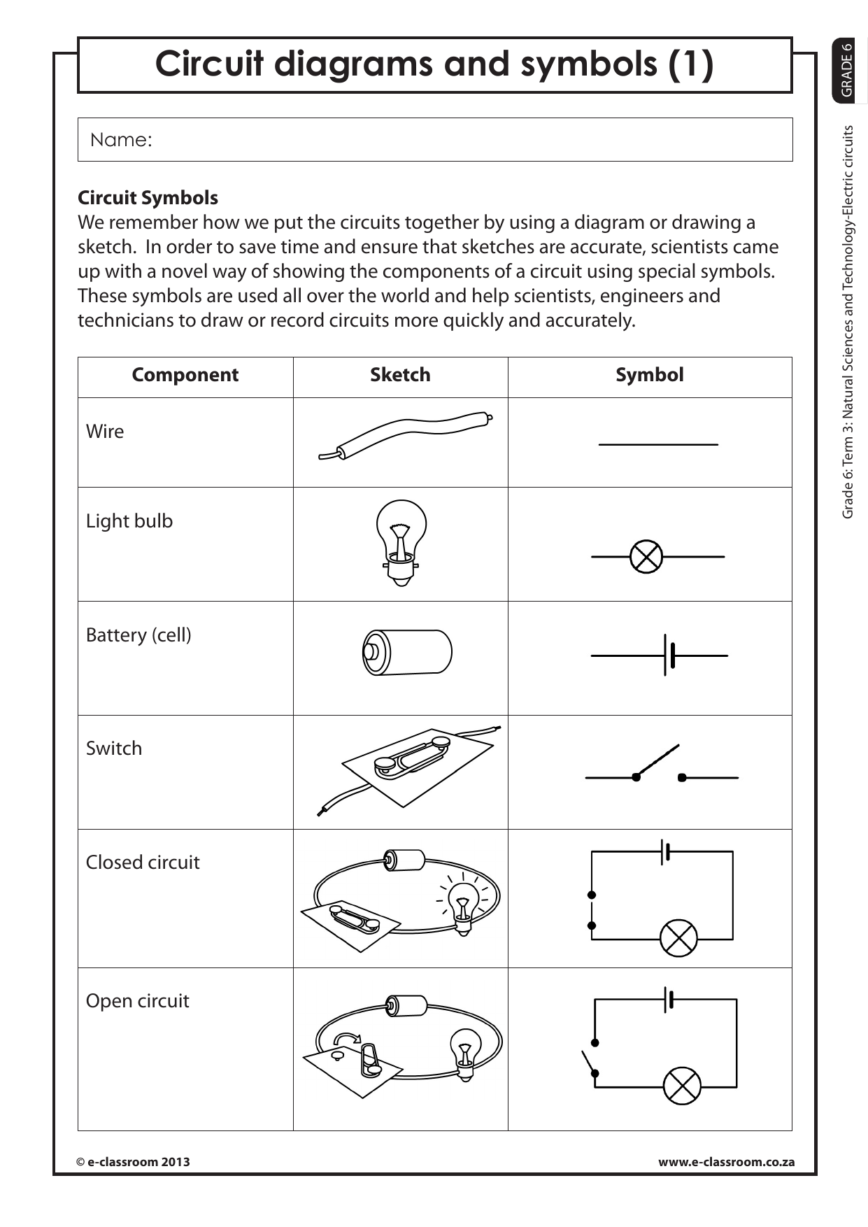
circuit-symbols-pdf
Source:http://bit.ly/Ues6FK

CIRCUIT ANALYSIS PDF
Source:http://lecturenotes.in/uploads/upload//5a47/5a475d/5a475df0e9b0666a9914a652/cjbt5jelq0iou0hpf9mcs3i5g.jpg
devoirs et exercice corrigés le dipole rc et rl pdf
PHYSIQUE CHIMIE 4éme année secondaire - MBahloulcom
- exercices corrigés sur le circuit rl
- regime transitoire exercice corrige
- dipole rl exercices corrigés pdf
- dipole rl exercice corrigé
- exercices corrigés dipole rc terminale s
- dipole rc exercices type bac
- circuit rc exercices corrigés
- exercice dipole rc corrigé
exercice rl corrigé
Série d 'exercices Bobine et dipôle RL - Kademiatn
- serie dipole rl corrigé
- dipole rc exercices type bac
- devoirs et exercice corrigés le dipole rc et rl pdf
- exercice régime transitoire corrigé
- exercice dipole rc corrigé
- dipole rc exercices corrigés bac
- exercices corrigés dipole rc terminale s
- serie dipole rc avec correction
exercice dipole rc corrigé
bac le dipôle rc - TuniSchool
- dipole rc exercices type bac
- condensateur exercices corrigés
- serie dipole rc avec correction
- serie d'exercice physique dipole rc
- exercices corrigés dipole rc terminale s
- devoirs et exercice corrigés le dipole rc et rl
- dipole rc exercices corrigés bac
- exercice rc bac
serie dipole rl corrigé
Série d 'exercices Bobine et dipôle RL - Kademiatn
- exercices corrigés sur le circuit rl
- exercice dipole rc corrigé
- devoirs et exercice corrigés le dipole rc et rl pdf
- dipole rl exercice corrigé pdf
- dipole rl exercices corrigés pdf
- dipole rc exercices type bac
- exercices corrigés dipole rc terminale s
- exercice régime transitoire corrigé