step 7 ladder logic examples
|
Programming with STEP 7
STEP 7 • From S5 to S7 Converter Manual Basic information for technical personnel describing the methods of implementing control tasks with STEP 7 and the S7-300/400 programmable controllers 6ES7810-4CA10-8BW0 STEP 7 Reference with • Ladder Logic (LAD) / Function Block Diagram (FDB) / Statement List (STL) for S7-300/400 manuals |
|
Working with STEP 7
Introduction to STEP 7 1 The SIMATIC Manager 2 Programming with Symbols 3 Creating a Program in 4 Creating a Program with Function Blocks and Data Blocks 5 Configuring the Central Rack 6 Downloading and Debugging the Program 7 Programming a Function 8 Programming a Shared Data Block 9 Programming a Multiple Instance 10 |
|
Ladder Logic (LAD) for S7-300 and S7-400 Programming
Ladder Logic (LAD) for S7- 300 and S7-400 Programming 138 Reference Manual 04/2017 A5E41524738-AA Description ROL_DW (Rotate Left Double Word) is activated by a logic \"1\" at the Enable (EN) Input The ROL_DW instruction is used to rotate the entire contents of input IN bit by bit to the left |
What is SIMATIC Step 7?
...the SIMATIC standard software for creating programmable logic control programs in Ladder Logic, Function Block Diagram, or Statement List for SIMATIC S7-300/400 stations. In this manual, you will get to know the basics of SIMATIC STEP 7.
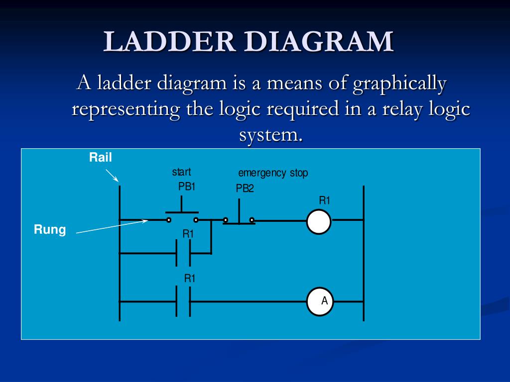
What is a ladder diagram example?
Ladder diagram examples and solutions to simple PLC logic functions. These are all basic PLC functions implemented in ladder logic. This is how the ladder diagram looks for a simple start/stop function. The function can be used to start and stop anything like a motor start/stop. In this ladder logic example, there are two inputs.
What are some examples of ladder logic programming?
Ladder Logic Programming Examples and PLC practical problems on Timers, Counters, Motor Control. PLC Programs with Real-Time world examples. To develop a ladder diagram for the ON/OFF temperature controller for the continuous process of heating of mixture. Develop a ladder program for wood saw cutter. Develop the ladder logic to fill the tank.
How to assign names to ladder logic elements?
summary of the steps involved in assigning names to Ladder Logic elements follows. Each step is then further divided into steps is subsequent paragraphs. Create the loops necessary for the ladder. Enter the discrete inputs to the ladder in the Reference list. For function block details, refer to CGiFB-1, UMiPAC-1, UM353-1, or UM354N-1.
Develop A Ladder Program For Wood Saw Cutter.
A wood saw cutter (W), a fan (F) and a lubrication pump (P) turns on when a START push button is pushed. Following is the stopping sequence:STOP push-button stops the saw only before fan stops it should run for an additional 5 sec to blow the chips away and also the tube pump is to run for 8 sec.Additionally, before it stops. if the saw has run more than 1 min, the fan should stay ON indefinitely. The fan may be turned OFF by pushing a separate fan reset switch. instrumentationtools.com
Develop The Ladder Logic to Fill The Tank.
Fill the tank up to 80%. When the tank is filled, turn ON the heater to raise the temperature up to 70 deg.when this temperature is reached, turn OFF the heater & open the outlet valve.When the level in the tank falls below 10%, close the output valve. instrumentationtools.com
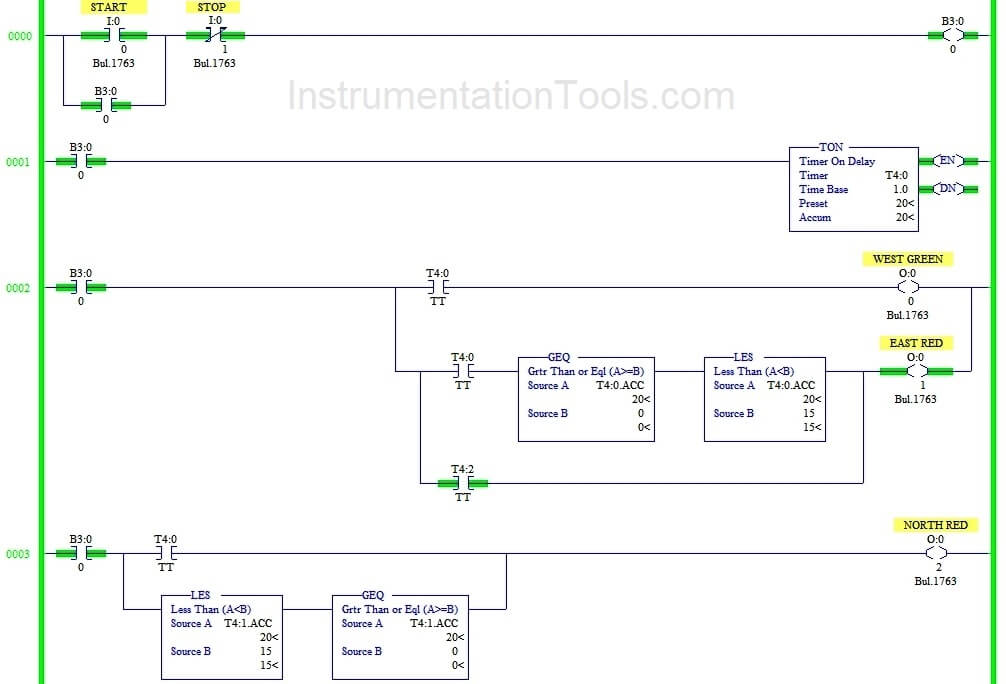
Develop Ladder Logic For Traffic Control.
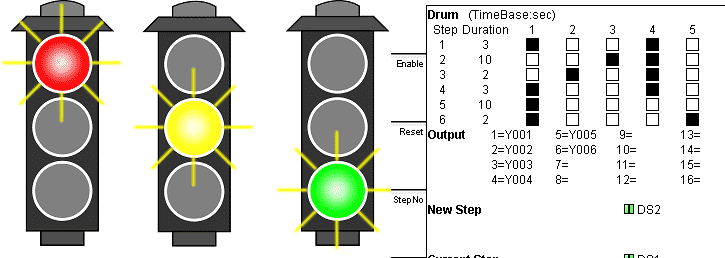
We have to control the traffic of 4 roads.The green light of each side is ON for 10 sec only one side at a time and the same time, the respected red light is ON for 30sec.The same sequence is followed by each side. instrumentationtools.com
Develop Ladder Logic For An Automatic Paint Process.
When the ON button is pushed, a stacker starts stacking plywood sheet at position A. stack height is controlled by PLC counter function. When 12 parts (stack) are placed on the conveyor, it turns ON and moves the stack at the position B. A sensor is used to stop the conveyor at B. At point B, paint is applied for 12 sec after painting is completed,
Develop Ladder Logic For Heat/Quench Station.
Steps: 1. Master PB is used to turn ON the process. 2. The object is placed on the mandrel 3. Both left & right start-up buttons are pressed. 4. Push stop PB to stop the process. 5. The object is raised from down to top by air pressure. A solenoid valve supplies this air to the pneumatic elevating cylinder. The lower limit switch is getting actuate
Develop Ladder Logic For The Coal Handling Process.
Process: The coal plant consist of the following main equipment 1. Storage tank: It stores coal in a huge amount & supplies it to the primary crusher as per requirement. 2. Primary crusher: It crushes the coal from a bigger size to smaller size & supplies it to secondary crusher. 3. Secondary crusher: Two crushers are used to decrease a load of cru
Develop Ladder Logic For The Automatic Door Opening of The Room.
Process: The process includes the following sequence of events. 1. When the start PB is pressed, the RTD will sense the temperature of the room. This will be considered as I/P to the analog input of PLC. 2. When the temperature of the room is greater than 250 c, then AC-I will be latched. When the temperature of the room is greater than 350 c, then
Develop The Ladder Program For The Process of Alternate Rotation of The Motor.
Process: – Here, the motor with two switches is used as shown. When the start button is pushed, the motor starts rotating towards the RLS and LLS. Sequence: 1. When ON button is pushed, the motor move the arm to the right limit switch position and waits for 30 sec. 2. The motor then cycles 75 times between the right to left switches and then stops
to Develop The Ladder Program For An Oven Using The Process Bits.
Process: – Process sequence is as follows 1. When the START button is pressed, the valve V1 is turned ON till HL (high level) is reached. 2. After HL is reached, V1 will close and heater and indicators are turned ON for 30 sec. 3. After 30 sec, valve V2 will turn ON for 20 sec to draw the hot water from the tank 4. If the STOP button is pressed dur
to Develop Ladder Logic Or The Heating Process.
Sequence: 1. When the START button is pressed, the valve V1 is turned ON till the high level (HL) is reached. 2. After HL is reached, valve V1 will close and heater and indicator turn ON for 30 sec. 3. After 30 sec, valve V2 will turn ON for 20 sec to draw the hot water from the tank. 4. If STOP input is activated during any time, the heater will t

PLC Basics: Ladder Logic

Ladder Logic (LAD) for S7-300 and S7-400 Programming

PLC Ladder Logic Programming Examples and Solutions in
|
SIMATIC Ladder Logic (LAD) for S7-300 and S7-400 Programming
This chapter provides the following examples of practical applications of the ladder logic instructions: • Controlling a conveyor belt using bit logic |
|
Ladder Logic (LAD) for S7-300 and S7-400 Programming
Legal information. Warning notice system. This manual contains notices you have to observe in order to ensure your personal safety as well as to prevent. |
|
Ladder Logic (LAD) for S7-300 and S7-400 Programming
Ladder Logic (LAD) for S7-300 and S7-400 Programming. A5E00706949-01. 11-7. 11.1.5 Overview of Programming Examples .....B-1. Overview of Rotate Instructions ... |
|
Ladder Logic (LAD) for S7-300 and S7-400 Programming
Ladder Logic (LAD) for S7-300 and S7-400 Programming. A5E00706949-01. 11-7. 11.1.5 Overview of Programming Examples .....B-1. Overview of Rotate Instructions ... |
|
Programming Guideline for S7-1200/1500
PLC migration to S7-1500 with STEP 7 (TIA Portal) https://support.industry Example. Table 3-8: Example for creating symbolic tags. Step. Instruction. 1. Open ... |
|
Programming with STEP 7
16 Jan 2011 ... Ladder allows you to track the power flow between power rails as it ... examples. Refer to the current Product Information for information ... |
|
Programming with STEP 7
We recommend that you familiarize yourself with the examples in the manual "Working with. STEP 7 V5. Ladder Logic Programming Language (LAD) ... |
|
Programming with STEP 7
Ladder allows you to track the power flow between power rails as it passes ... examples. Refer to the current Product Information for information on memory ... |
|
S7-200 Programmable Controller
Chapter 6 (S7-200 Instruction Set) provides descriptions and examples of programming instructions supported by the S7-200. -. Chapter 7 (Communicating over a |
|
SIMATIC Programming with STEP 7
27 Mar 1998 We recommend that you familiarize yourself with the examples in the manual. "Working with STEP 7 V5. ... Ladder Logic and. Function Block Diagram. |
|
SIMATIC Ladder Logic (LAD) for S7-300 and S7-400 Programming
This manual is valid for release 5.6 of the STEP 7 programming software package. Compliance with Standards Example: Word Logic Instructions . |
|
Ladder Logic (LAD) for S7-300 and S7-400 Programming
This manual is valid for release 5.4 of the STEP 7 programming software package. Compliance with IEC 1131-3. LAD corresponds to the “Ladder Logic” language |
|
Statement List (STL) for S7-300 and S7-400 Programming
This manual is valid for release 5.6 of the STEP 7 programming software package. Example. STL Program. A. I 1.0. AN. I 1.1. = Q 4.0. Relay Logic. |
|
Ladder Logic (LAD) for S7-300 and S7-400 Programming
8 kwi 2010 This manual is valid for release 5.5 of the STEP 7 programming software package. ... Example: Counter and Comparison Instructions . |
|
Programming Guideline for S7-1200/S7-1500
Application Examples and other Siemens publications – e.g. Catalogs – the PLC migration to S7-1500 with STEP 7 (TIA Portal). |
|
Programming with STEP 7
16 sty 2011 We recommend that you familiarize yourself with the examples in the ... Ladder Logic (or LAD) is a graphic representation of the STEP 7 ... |
|
Programming with STEP 7
We recommend that you familiarize yourself with the examples in the manual "Working with Ladder Logic (or LAD) is a graphic representation of the STEP 7 ... |
|
Working with STEP 7
the SIMATIC standard software for creating programmable logic control programs in Ladder. Logic Function Block Diagram |
|
SIMATIC Ladder Logic (LAD) for S7-300 and S7-400 Programming
This manual is valid for release 5.3 of the STEP 7 programming software package. example an open dialog box or an active window. |
|
Scaling and Unscaling Analog Values
7 cze 2006 Programming Example in Ladder Logic. Scaling and Unscaling Analog ... examples and other Siemens publications - e.g. Catalogs - then the. |
|
Ladder Logic (LAD) for S7-300 and S7-400 Programming - Siemens
A Programming Examples B Working with Ladder Logic C SIMATIC Ladder Logic (LAD) for S7-300 and S7-400 Programming Reference Manual 05/2010 |
|
Programming with STEP 7 - RS Components
We recommend that you familiarize yourself with the examples in the manual " Working with Ladder Logic (or LAD) is a graphic representation of the STEP 7 |
|
Ladder Logic
This manual is valid for release 3 0 of the STEP 7 programming software package blocks (for example blocks for IEC functions or closed-loop controller |
|
SIMATIC Working with STEP 7 - FER
Using practical exercises, we will show you how easy it is to program in Ladder Logic, Statement List, or Function Block Diagram with STEP 7 Detailed |
|
Siemens plc programming examples PDF
then double clicN on the line of networN1 as shown below More See http:// bin95 com/Siemens-Training/siemens-plc-programming-examples htm |
|
Siemens Plc Programming Examples
Tutorial of siemens Step 7 PLC programming using simatic PLC Examples Industrial Automation and Mechatronics SIMATIC S7 1200 SIMATIC Controllers |
|
Siemens S7-1200 Easy Book
TIA Portal includes STEP 7 for S7-1200 programming and WinCC for designing Basic panel example, use ladder logic (LAD) to create the program code |
|
Statement List (STL) for S7-300 and S7-400 Programming
This manual is valid for release 5 4 of the STEP 7 programming software package Example Relay Logic STL Program A I 1 0 A I 1 1 = Q 4 0 Power rail |
|
Siemens S7 300 Programming Ladder Logic Examples For
TUTORIAL OF SIEMENS STEP 7 PLC PROGRAMMING USING SIMATIC MANAGER TIMERS SIMATIC LADDER LOGIC LAD FOR S7 300 AND S7 400 |
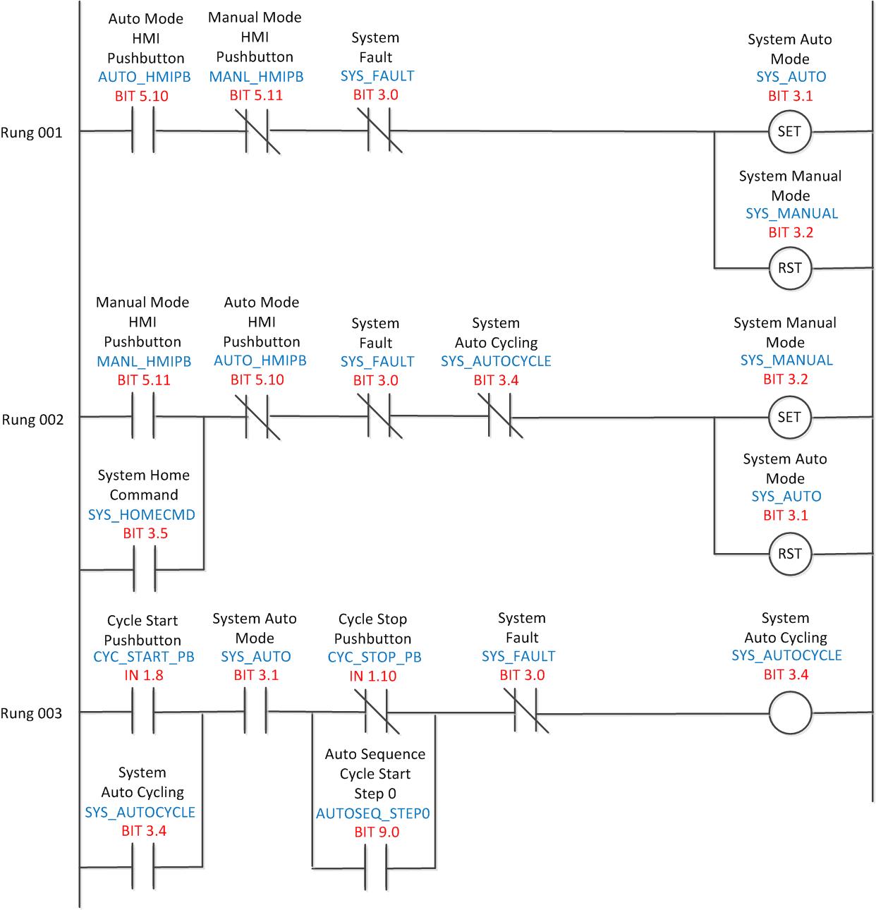
![DIAGRAM] Plc Ladder Logic Diagrams FULL Version HD Quality Logic DIAGRAM] Plc Ladder Logic Diagrams FULL Version HD Quality Logic](https://i1.wp.com/www.electroniclinic.com/wp-content/uploads/2019/09/plc-based-traffic-light-control-system-ladder-logic-diagram.jpg?ssl\u003d1)



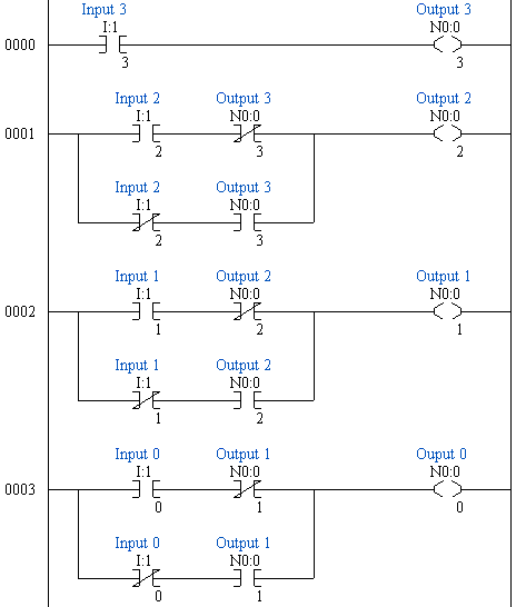




![PDF] PLC Programming Methods and Applications - Ebook Free PDF] PLC Programming Methods and Applications - Ebook Free](https://i1.wp.com/www.electroniclinic.com/wp-content/uploads/2019/09/plc-based-load-management-circuit-diagram.png?ssl\u003d1)

