altium designer pdf tutorial full
|
TU0117 Getting Started with PCB Design
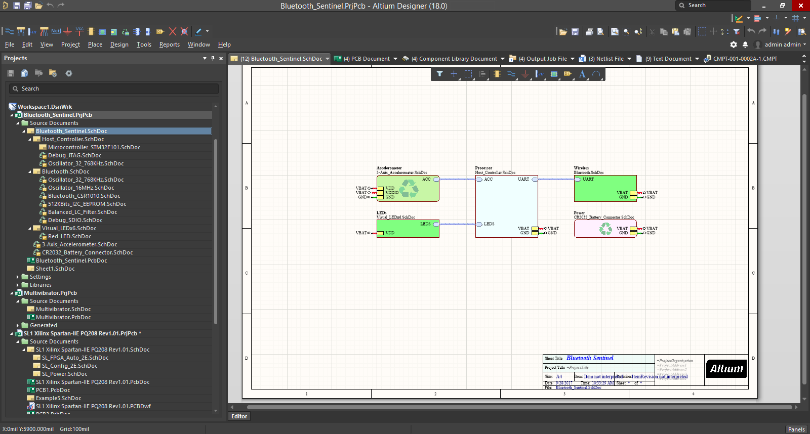
environment This tutorial will get you started with creating a PCB project based on an astable multivibrator design If you are new to Altium Designer then you might like read the guide Welcome to the Altium Designer Environment for an explanation of the interface information on how to use panels and managing design documents |
|
Altium Designer Guide
Part 1: Beginning Guide This guide is a beginner’s guide to PCB design using Altium Designer and is geared towards the following individuals: Possess ample theoretical electronics knowledge Has little or no PCB design experience Has little or no Altium Designer experience Beginning Guide |
|
ALTIUM TUTORIAL SESSION 2017 EE209
New Project/File Add libraries Choose parts Wire/Bus Power/Ground/Net label Annotation/values Compile Update PCB |
|
Module 1: Getting Started With Altium Designer
Altium Designer includes tools for all design tasks: from schematic and HDL design capture circuit simulation signal integrity analysis PCB design and FPGA-based embedded system design and development In addition the Altium Designer environment can be customized to meet a wide variety of user requirements |
How do I save a schematic sheet in Altium Designer?
Once the schematic sheet is open, press use the ‘CTRL + S’ shortcut to save the file using a reasonable name (for example, ‘LDO-Schematic.SchDoc’). For our design, we only need a handful of parts – I’ve ended up choosing: I’ll show you how we place and connect these parts together in Altium Designer now.
How do I create a new PCB design in Altium Designer?
The easiest way to create a new PCB design in Altium Designer is to use the PCB Board Wizard, which allows you to choose from industry-standard board outlines as well as create your own custom board sizes. At any stage you can use the Back button to check or modify previous pages in the wizard.
How can Altium design integrate with mechanical CAD packages?
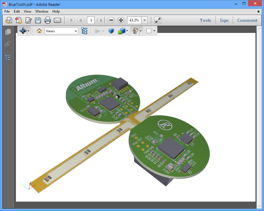
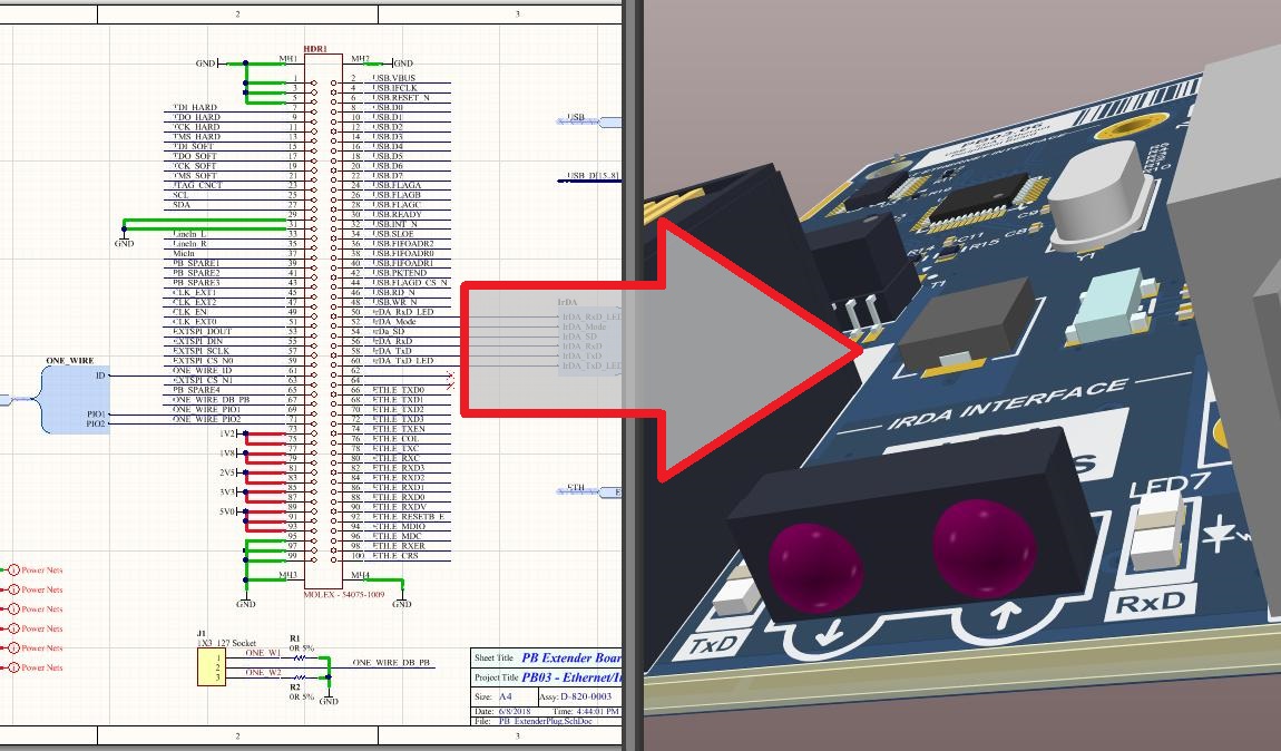
Furthermore, precise component clearance checking and even assembling entire PCBs and external, free-floating 3D objects is possible. This creates a new level of design integration with mechanical CAD packages, right within Altium Designer.
What is Altium Designer?
Altium Designer includes tools for all design tasks: from schematic and HDL design capture, circuit simulation, signal integrity analysis, PCB design, and FPGA-based embedded system design and development. In addition, the Altium Designer environment can be customized to meet a wide variety of user requirements.
Schematic
New Project/File Add libraries Choose parts Wire/Bus Power/Ground/Net label Annotation/values Compile Update PCB cdn.auckland.ac.nz
PCB
Component placement Redefine Board Shape Mounting Holes Design Rules Routing Configuration Polygon Pour Design Rule Check (DRC) cdn.auckland.ac.nz
WIRE/BUS
It is now time to wire these parts together. a. You can either click the ‘Place Wire’ icon from the upper toolbar or select Place > Wire. Both are illustrated here. b. Once you click this icon your cursor will turn into a crosshair with a black X on it. Once you hover over a valid place to connect a wire the X will turn red. If the X does not turn
POWER/GROUND/NET LABEL
Now it’s time to add the Power and Ground nets to the schematic Click the ‘VCC Power Port’ button that is next to the ‘Place Wire’ button and place them in the places shown in the image on the next page ports will be renamed from ‘VCC’ to corresponding values. Naming ports is the same thing as connecting them with a wire but it is a more elegant so
ANNOTATION
It is now time to annotate all of the unnamed components Add more descriptive comments to the ports, this will make them easier to find on the PCB later Double click on the AC input socket and Change the comment ‘=Value’ and make it say ‘AC Input Socket’ You can add text to your schematic to make it easier to understand. Place Text String No t
COMPILE
Now the Schematic is ready and we can design the PCB file. Before transferring to PCB, make sure your schematic design has no error. cdn.auckland.ac.nz
in Project > Compile PCB project ‘nameOfProject.PrjPcb’
When the project is compiled, all warnings and errors will displayed in the Messages panel. The panel will only appear automatically if there are errors detected. If there are errors, work through each one, checking your circuit and ensuring that all wiring and connections are correct. Here is a sample error message which is not for our project fil
UPDATE PCB
We are now ready to update the PCB file Design > Update PCB Document ‘nameOfProject.PcbDoc’ Scroll to the bottom of the window that pops up and uncheck the box next to the room that the program is trying to add Click Validate Changes, make sure all of the changes get validated Click Execute Changes, this will add all of the components and nets to y
COMPONENT PLACEMENT
We will now arrange the components on the board Go to the PCB document Begin dragging the footprints of the components over to the board The footprints and the designators can once again be rotated using Spacebar while they are being dragged To get a better view at any time you can use View > Fit Document or you can use Page Up and Page Down (or Ct
REDEFINE BOARD SHAPE
Redefine the board shape (The black background on the screen is the board) View > Board Planning Mode a green screen will appear. Then go to Design > Redefine Board Shape The cursor will turn into a crosshair Zoom in to get a closer view of the grid and click the first corner of the new board shape that you want; continue to the next corner and cli
ROUTING
Choose the routing layer; Top layer or Bottom Layer Route > Interactive Routing cursor will turn into a crosshair ; The Start from a pad and find a suitable path to the destination which is defined by a thin line. You can change track angles by pressing spacebar while being in ‘place track’ mode. Remember to zoom in/out to have a better view of the
Add your initials and a revision number
Use Place > String to add the string to an empty space on your board Double click the string to open its properties Change the text field to your course name and group number e. ‘Course name - Group number’ cdn.auckland.ac.nz
Add a keepout layer to the perimeter of your board
some manufactures will use this to cut your board Select ‘Keep-Out Layer’ from the tabs at the bottom of the designer window; up to this point we have been working from the ‘Bottom Layer’ Make sure the Keepout layer is selected then Add a Line using Place > Line. This will be similar to redefining the shape of the board where you can zoom in at the
DESIGN RULE CHECK
Design Rule Checking (DRC) is a powerful automated feature that checks both the logical and physical integrity of your design. Checks are made against any or all enabled design rules. Go to Tools > Design Rule Check Click on “Run Design Rule Check” The report lists each rule that was tested, as specified in the Design Rule Checker dialog. Each viol

Altium Designer 22 Tutorial

Altium Designer Quick-Start Tutorial with Phil Salmony from Phils Lab

How to use Altium Designer complete tutorial
|
TU0117 Getting Started with PCB Design
Welcome to the world of Altium Designer – a complete electronic product development environment. This tutorial will get you started with creating a PCB |
|
Altium Designer Guide
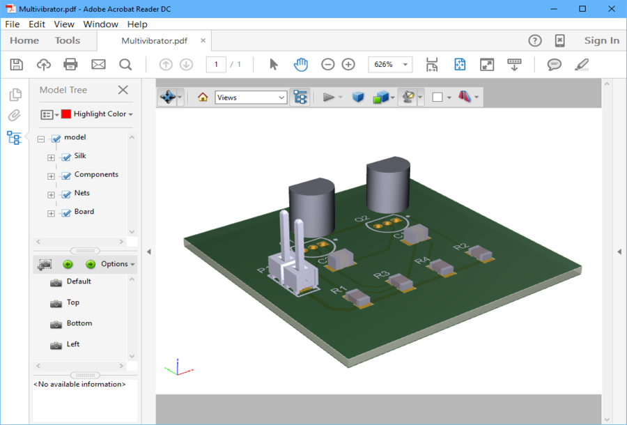
Must learn at least a basic form of CAD software This is based off the current version of Altium Designer ... I have included a Smart PDF of the. |
|
Module 1: Getting Started With Altium Designer
Underlying the Altium Designer environment is a software integration platform that brings together all the tools necessary to create a complete environment |
|
Altium I (Circuit Design & Simulation)
Feb 3 2022 [B1] Complete PCB Design Using OrCad Capture and Layout Kraig ... Do complete this tutorial ... L298_Motor_Driver_Board_Datasheet.pdf. |
|
Creating and Modifying a Project with Altium Designer EEL3923
We will now add a schematic and a PCB to the current project. a. Right click on the project The libraries that we will be using for this tutorial are:. |
|
Guide dInitiation à la conception de circuits imprimés
Pour des informations détaillées sur la gestion et la création de projets dans Altium Designer cliquez ici. 1. Créez un nouveau projet de PCB. File » New » |
|
Defining & Running Circuit Simulation Analyses
Altium Designer allows you to run an array of circuit simulations directly from a schematic. In the following sections of the tutorial we will simulate the |
|
Shortcut Keys - Legacy documentation refer to the Altium Wiki for
Recompile the current design project Toggle full screen mode. Left-click ... Cross probe to object on both schematic document and PCB. |
|
AltiumLive 2017: Introduction to PCB Design with Altium Designer 18
Releasing a design to fabrication while under the gun to get it finished can be risky but it doesn't have to be if you use Outjobs. ? Complete |
|
Welcome to the Altium Designer Environment
May 22 2008 Altium Designer brings a complete electronic product development ... opened and edited in the Schematic Editor |
|
TU0117 Getting Started with PCB Design - Altium
Welcome to the world of Altium Designer – a complete electronic product development This tutorial will get you started with creating a PCB project based on an and send them to various output media (direct print, PDF and file generation) |
|
Introduction to Altium Designerpdf
Ability to design simple Schematic and PCB You can see samples of Printed Circuit Board (PCB) at https://learn sparkfun com/tutorials/pcb-basics |
|
Guide de demarrage Altium Designer - Alexandre Boyer
Pour la sauvegarder au format PDF, cliquez sur Print et utilisez l'imprimante PDF On obtient ainsi le masque pour le top layer VII Créer une nouvelle librairie |
|
Altium I (Circuit Design & Simulation) - UBC ECE
Mechanical and PCB design support available 2hrs per lab session, Altium Designer • Walk-through Tutorial A complete product development system |
|
Altium Tutorial - University of Florida
Creating and Modifying a Project with Altium Designer EEL3923/EEL4924 Design 1 and 2 – University of Florida, Electrical and Computer Eng Document |
|
Altium Designer Guide - UTK-EECS
tutorial, It is important to understand when it is absolutely Altium Designer This is based off the current version of Altium Designer, Save as 'Atmega8 QFP Atmel Microcontroller pdf ' USB-B Complete the Schematic Copy and |
|
Getting started with PCB design (pdf) - Electrical and Computer
12 fév 2008 · Welcome to the world of Altium Designer – a complete electronic This tutorial will get you started with creating a PCB project based on an |
|
ALTIUM TUTORIAL SESSION 2017 EE209
We will now add a schematic and a PCB to the current project Right click on library For a list of whole available components in ECE please see this webpage : |
|
Altium Designer Learning - Documents and E-books
[Free Download] Altium Designer Learning [PDF] [EPUB] Altium Designer offers a complete set of tools Altium Designer 14 Circuit Design Basics tutorial and |







![Udemy] Learn PCB Design in Altium Designer Free Download Udemy] Learn PCB Design in Altium Designer Free Download](https://www.coursehero.com/doc-asset/bg/1410e2b51ccf3e510062706213ba49fbe1422451/splits/80821004/split-0-page-1-html-bg-unsplit.png)
