 30RB/RQ 017-160 - Régulation Pro-Dialog+
Carrier. 30RB/RQ 017-160. Régulation Pro-Dialog+. PRO-DIALOG +. Carrier. AQUASNAP. AQUASNAP. Carrier. \MAINMENUSTATUS. CAPB_T. DEM_LIM. AP. CTRL PHI. INSTOP.
 30RB 039-160 / 30RQ 039-160
Diagnostic rapide des éventuels incidents et de leur historique par la régulation Pro-Dialog+. Les unités Carrier 30RB/RQ sont conçues pour un respect aisé de ...
 30RB/30RQ 017-160 Pro-Dialog+ Control
The compressors in circuit A are labelled A1. A2 and A3. Those in circuit B are B1 and B2. The following abbreviations are used frequently: CCN. Carrier
 AHI Carrier
devices fans and of the water heat exchanger water pump for optimum energy efficiency. Pro-Dialog+ interface. \MAINMENUSTATUS. Circuit B Total Capacity.
 30RB/30RBY 039-160 “A” Air-Cooled Liquid Chillers
To do this consult the 30RB/RQ 017-160 Pro-Dialog+ control manual. 1.2 qualified by Carrier are available via the Carrier spare parts network on request ...
 AHI Carrier
Pro-Dialog controls compressor start-up needed to maintain the desired heat exchanger entering or leaving water temperature. In cooling mode it controls the
 AHI Carrier
Touch Pilot Junior Control manual for the 30RB/30RQ 017-160 series. 30RQS on the board refer to the 30RB/RQ Touch Pilot Junior control manual. Other ...
 AQUASNAP 30RB / 30RQ 30RBY / 30RQY
For the use of the control system refer to the Pro-Dialog + control manual. 30RB-RQ units use a R-410A refrigerant charge. For your information
 30RB 039-160 / 30RQ 039-160
historique par la régulation Pro-Dialog+. Les unités Carrier 30RB/RQ sont conçues pour un respect aisé de ces directives la.
 30RB/30RQ 017-040 A 30RBY 017-033 A
du système de régulation consulter le Manuel de la régulation Pro-Dialog +. ... Les unités 30RB-RQ utilisent une charge de fluide frigorigène R-410A.
 AHI Carrier
Pro-Dialog+ combines intelligence with operating simplicity. 30RB/RQ. 017. 021. 026. 033. 040. Power circuit. Nominal power supply. V-ph-Hz.
 30RB 039-160
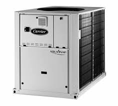
PRO-DIALOG +. Model shown is with low-noise option. Air-Cooled Liquid Chillers. 30RB 039-160. Nominal cooling capacity 40-160 kW.
 AHI Carrier
Pro-Dialog+ combines intelligence with operating simplicity. 30RB/RQ - units with hydronic module ... Source: EU Regulation 813/2013.
 30RA/RH “B” 30RY/RYH “B” Régulation PRO-DIALOG
- Mode CCN: la machine est contrôlée à l'aide de commandes en provenance du réseau CCN (Carrier. Comfort Network). Dans ce cas un câble de communi- cation est
 30RBS/30RBSY 039-160 « C »
Sur le fonctionnement du régulateur se reporter au manuel de régulation Touch Pilot Junior pour unités 30RB/RQ. ... professionnel qualifié.
 AQUASNAP 30RB / 30RQ 30RBY / 30RQY
For the use of the control system refer to the Pro-Dialog + control manual. 30RB-RQ units are shipped with a full operating charge of refrigerant.
 AHI Carrier
Touch Pilot Junior Control manual for the 30RB/30RQ 017-160 series 3.5 - Applicable rules for units incorporated into an air duct network .
 61WG / 30WG 020-090 Régulation Pro-Dialog+
Pro-Dialog contrôle: • le démarrage des compresseurs pour réguler la boucle d'eau. • les pompes
AQUASNAP30RB / 30RQ30RBY / 30RQY
Installation, operation and maintenance instructionsPRO-DIALOG +
Cop_GB_.indd 113-06-2011 9:12:14
30RB/30RQ30RBY/30RQY
ENGLISH
Air-cooled liquid chillers and reversible cycle air-water heat pump with integrated hydronic module
Cop_GB_.indd 213-06-2011 9:12:14
GB - 1
ENGLISH
30RB/30RQ - 30RBY/30RQY
Air-cooled liquid chillers and reversible air-to-water heat pumps with integrated hydronic module For the use of the control system, refer to the Pro-Dialog + control manual.Contents
PagePhysical data
........................................................................................................................................................................ 2-5
Electrical data
...................................................................................................................................................................... 2-5
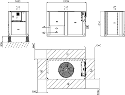
Dimensions and location of hydraulic connections
................................................................................................. 6-8
User interface and main switch
...................................................................................................................................... 9
Clearance for horizontal outlet unit
.............................................................................................................................. 9
Clearance for vertical outlet unit
.................................................................................................................................... 9
General information and hydronic module ............................................................................................................... 10-12
Water connections
............................................................................................................................................................. 12-14
Electrical connections
....................................................................................................................................................... 15
Refrigerant charge
............................................................................................................................................................. 16
Electronic control
............................................................................................................................................................... 16
Start-up ................................................................................................................................................................................. 17
Compressor replacement................................................................................................................................................. 17
Pump replacement
............................................................................................................................................................ 18
Unit protection devices
.................................................................................................................................................... 18-19
Operating limits and operating range
.......................................................................................................................... 19
General maintenance
........................................................................................................................................................ 20
Maintenance ....................................................................................................................................................................... 20
Final recommendations
.................................................................................................................................................... 20
Troubleshooting
................................................................................................................................................................. 21
Start up date _________________________
Equipment sold by:
_________________________________________________Contract No: _________________________________Installed by:
_______________________________________________________Contract No: _________________________________
Site address
____________________________Equipment type and serial No:
30RB ___________________________________________________________________
30RQ ___________________________________________________________________
ELECTRICAL DATA:
Supply voltage
Ph 1: _______________V Ph 2: _______________V Ph 3: ________________VNominal voltage:
_________________________________________V % network voltage ____________________________Current draw
Ph 1: _______________A Ph 2: _______________A Ph 3: _________________AControl circuit voltage:
_____________________________________V Control circuit fuse__________________________AMain circuit breaker rating
________________PHYSICAL DATA
Coil:Plate heat exchanger:
Entering air temp.:
____________________________°C Entering water temp.: _____________________°CLeaving air temp.:
____________________________°C Leaving water temp.: ______________________°CLoss of head (water): ______________________kPa
SAFETY DEVICE SETTING:
High pressure switc
h: cut-out: __________________kPa cut-in: ________________________kPaOil level
_______________________________OPTIONS:
Commissioning engineer
_________________Customer agreement
Name :______________________________________ Date: ___________________________________ Note Complete this start-up list at the time of installation.Start-up check list
128H68-GB.indd 113-06-2011 8:32:42
30RBGB - 2
30RB017 021 026 033
PowerV-ph-Hz 400-3-50
Voltage range
V 340-460
Starting current*
A 75 95 118 118
Maximum power drawn (Vn) **
kW 7,8 9,1 11,0 13,8Rated current***
A 8 12 16 17
Maximum power drawn (Vn) ****
A 13 16 20 24
Maximum power drawn (Vn +/-15%) †
A 15 18 23 27
* Max. starting current within the operation limits (corresponding to the current of locked rotor in the compressor)
** Input power when the unit is at its operation limits (evaporation temperature = 10°C, condensation temperature = 65°C) and at the rated voltage (400 V)
*** The currents shown refer to Eurovent conditions (evaporator water inlet and outlet temperature = 12/7°C with air to the condenser at 35°C)
**** Max. operating current related to the max. input power and rated voltage (400 V) † Max. operating current related to the max. input power and within the range 340-460 VTable II: Electrical data - Model RB
30RB017 021 026 033
Operating weight
with hydronic moduleKg 189 208 255 280
without hydronic moduleKg 173 193 237 262
Refrigerant charge R-410A
Kg 5,5 6,4 5,8 8,6
Compressor
One scroll compressor
Evaporator
One plate heat exchanger
Net water volume
l 1,52 1,9 1,71 2,28Water connections (MPT gas)
inches 1 1 1-1/4 1-1/4Maximum water pressure
kPa 1000 1000 1000 1000 (unit without hydronic module)Maximum water pressure
kPa 400 400 400 400 (unit with hydronic module)Hydronic module
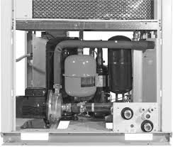
Pump, mesh ?lter, expansion tank, ?ow switch, pressure gauges, automatic air purge valve and drain plug and safety valve.
PumpOne single-speed pump
Water inlet connection (MPT gas)
inches 1-1/4 1-1/4 1-1/4 1-1/4Water outlet connection (MPT gas)
inches 1 1 1-1/4 1-1/4Closed expansion tank water volume
l 5 5 8 8Pre-charge of expansion vessel
bar 1,5 1,5 1,5 1,5Water ?ll system (option)
Inlet/outlet diameter (MPT gas)
inches 1/2 1/2 1/2 1/2Condenser
One, copper tubes and aluminium ?ns
Fan Two,axial type with two speeds Two-speed axial typeDiameter
mm 495 495 710 710No. of blades
3 3 7 7
Air ?ow (high speed)
l/s 2212 2212 3530 3530Fan speed (high speed)
g/min 870 870 900 900Table I: Physical data - Model RB
Physical data and electrical data - Model RB
128H68-GB.indd 213-06-2011 8:32:42
30RQGB - 3
ENGLISH
30RQ017 021 026 033
PowerV-ph-Hz 400-3-50
Voltage range
V 340-460
Starting current*
A 75 95 118 118
Maximum power drawn (Vn) **
kW 7,8 9,1 11,0 13,8Nominal current drawn***
kW 8 12 16 17Maximum power drawn (Vn) ****
A 13 16 20 24
Maximum power drawn (Vn +/-15%) †
A 15 18 23 27
* Max. starting current within the operation limits (corresponding to the current of locked rotor in the compressor)
** Input power when the unit is at its operation limits (evaporation temperature = 10°C, condensation temperature = 65°C) and at the rated voltage (400 V)
*** The currents shown refer to Eurovent conditions (evaporator water inlet and outlet temperature = 12/7°C with air to the condenser at 35°C)
**** Max. operating current related to the max. input power and rated voltage (400 V) † Max. operating current related to the max. input power and within the range 340-460 VTable II: Electrical data - Model RQ
30RQ017 021 026 033
Operating weight
with hydronic moduleKg 206 223 280 295
without hydronic moduleKg 191 208 262 277
Refrigerant charge R-410A
Kg 6,4 7,7 7,6 9,5
Compressor
One scroll compressor
Evaporator
One plate heat exchanger
Net water volume
l 1,52 1,9 2,28 2,85Water connections (MPT gas)
inches 1 1 1-1/4 1-1/4Maximum water pressure
kPa 1000 1000 1000 1000 (unit without hydronic module)Maximum water pressure
kPa 400 400 400 400 (unit with hydronic module)Hydronic module
Pump, mesh ?lter, expansion tank, ?ow switch, pressure gauges, automatic air purge valve and drain plug and safety valve.
PumpOne single-speed pump
Water inlet connection (MPT gas)
inches 1-1/4 1-1/4 1-1/4 1-1/4Water outlet connection (MPT gas)
inches 1 1 1-1/4 1-1/4Closed expansion tank water volume
l 5 5 8 8Pre-charge of expansion vessel
bar 1,5 1,5 1,5 1,5Water ?ll system (option)
Inlet/outlet diameter (MPT gas)
inches 1/2 1/2 1/2 1/2Condenser
One, copper tubes and aluminium ?ns
Fan Two,axial type with two speeds Two-speed axial typeDiameter
mm 495 495 710 710No. of blades
3 3 7 7
Air ?ow (high speed)
l/s 2217 1978 3530 3530Fan speed (high speed)
g/min 870 870 900 900Table I: Physical data - Model RQ
Physical data and electrical data - Model RQ
128H68-GB.indd 313-06-2011 8:32:42
30RBYGB - 4
30RBY017 021 026 033
PowerV-ph-Hz 400-3-50
Voltage range
V 360 - 440
Starting current*
A 75 95 118 118
Maximum power drawn (Vn) **
kW 8,0 9,3 11,2 14,0Rated current***
W 8 12 20 21
Maximum power drawn (Vn) ****
A 13 16 20 24
Maximum power drawn (Vn +/-15%) †
A 15 18 23 27
* Max. starting current within the operation limits (corresponding to the current of locked rotor in the compressor)
** Input power when the unit is at its operation limits (evaporation temperature = 10°C, condensation temperature = 65°C) and at the rated voltage (400 V)
*** The currents shown refer to Eurovent conditions (evaporator water inlet and outlet temperature = 12/7°C with air to the condenser at 35°C)
**** Max. operating current related to the max. input power and rated voltage (400 V) † Max. operating current related to the max. input power and within the range 360-440 VTable II: Electrical data - Model RBY
30RBY017 021 026 033
Operating weight**
with hydronic moduleKg 209 228 255 280
without hydronic moduleKg 193 213 237 262
Refrigerant charge R-410A
Kg 5,5 6,4 5,8 8,6
Compressor
One scroll compressor
Evaporator
One plate heat exchanger
Net water volume
l 1,52 1,9 1,71 2,28Water connections (MPT gas)
inches 1 1 1-1/4 1-1/4Maximum water pressure
kPa 1000 1000 1000 1000 (unit without hydronic module)Maximum water pressure
kPa 400 400 400 400 (unit with hydronic module)Hydronic module
Pump, mesh ?lter, expansion tank, ?ow switch, pressure gauges, automatic air purge valve and drain plug and safety valve.
PumpOne single-speed pump
Water inlet connection (MPT gas)
inches 1-1/4 1-1/4 1-1/4 1-1/4Water outlet connection (MPT gas)
inches 1 1 1-1/4 1-1/4Closed expansion tank water volume
l 5 5 8 8Pre-charge of expansion vessel
bar 1,5 1,5 1,5 1,5Water ?ll system (option)
Inlet/outlet diameter (MPT gas)
inches 1/2 1/2 1/2 1/2Condenser
One, copper tubes and aluminium ?ns
Fan Two radial fans with backward blades One axial fanDiameter
mm 495 495 710 710No. of blades
3 3 7 7
Outlet static pressure
Pa 80 80 80 80
Air ?ow (high speed)
l/s 2212 2212 3530 3530Fan speed (high speed)
g/min 870 870 900 900Table I: Physical data - Model RBY
Physical data and electrical data - Model RBY
128H68-GB.indd 413-06-2011 8:32:43
30RQYGB - 5
ENGLISH
30RQY017 021 026 033
PowerV-ph-Hz 400-3-50
Voltage range
V 360 - 440
Starting current*
A 75 95 118 118
Maximum power drawn (Vn) **
kW 8,0 9,3 11,2 14,0Nominal current drawn***
W 8 12 20 21
Maximum power drawn (Vn) ****
A 13 16 20 24
Maximum power drawn (Vn +/-15%) †
A 15 18 23 27
* Max. starting current within the operation limits (corresponding to the current of locked rotor in the compressor)
** Input power when the unit is at its operation limits (evaporation temperature = 10°C, condensation temperature = 65°C) and at the rated voltage (400 V)
*** The currents shown refer to Eurovent conditions (evaporator water inlet and outlet temperature = 12/7°C with air to the condenser at 35°C)
**** Max. operating current related to the max. input power and rated voltage (400 V) † Max. operating current related to the max. input power and within the range 360-440 VTable II: Electrical data - Model RQY
30RQY017 021 026 033
Operating weight**
with hydronic moduleKg 226 243 280 295
without hydronic moduleKg 211 228 262 277
Refrigerant charge R-410A
Kg 6,4 7,7 7,6 9,5
Compressor
One scroll compressor
Evaporator
One plate heat exchanger
Net water volume
l 1,52 1,9 2,28 2,85Water connections (MPT gas)
inches 1 1 1-1/4 1-1/4Maximum water pressure
kPa 1000 1000 1000 1000 (unit without hydronic module)Maximum water pressure
kPa 400 400 400 400 (unit with hydronic module)Hydronic module
Pump, mesh ?lter, expansion tank, ?ow switch, pressure gauges, automatic air purge valve and drain plug and safety valve.
PumpOne single-speed pump
Water inlet connection (MPT gas)
inches 1-1/4 1-1/4 1-1/4 1-1/4Water outlet connection (MPT gas)
inches 1 1 1-1/4 1-1/4Closed expansion tank water volume
l 5 5 8 8Pre-charge of expansion vessel
bar 1,5 1,5 1,5 1,5Water ?ll system (option)
Inlet/outlet diameter (MPT gas)
inches 1/2 1/2 1/2 1/2Condenser
One, copper tubes and aluminium ?ns
Fan Two radial fans with backward blades One axial fanDiameter
mm 495 495 710 710No. of blades
3 3 7 7
quotesdbs_dbs23.pdfusesText_29[PDF] 30RA/RY - 30RH/RYH Régulation PRO-DIALOG - Carrier
[PDF] 30RA/RY - 30RH/RYH Régulation PRO-DIALOG - Carrier
[PDF] OPERATION AND SERVICE MANUAL SUPRA 750Mt_, 850Mt_
[PDF] Québec Métiers d 'avenirpdf
[PDF] Dares Analyses 2016-056 - Les jeunes en emploi d 'avenir
[PDF] Declaración de Derechos ( Bill of Rigths ) de los Estados Unidos de
[PDF] Propuesta de Servicios Profesionales
[PDF] distance carte échelle = distance réelle - Académie de Nancy-Metz
[PDF] Demande de Carte de réduction - Oncf
[PDF] Conditions générales CARTE FNAC + - Resilierfr
[PDF] RÉPUBLIQUE TOGOLAISE
[PDF] carte administrative idf - Driea
[PDF] Inscriptions administratives 2017/2018 - L 'Université Paris Descartes
[PDF] Images correspondant ? carte afrique avant colonisation filetype:pdf
