 Telescope Resolution – How much detail can you see?
calculated using the simple formula: 134. R = -----. D For example a pair of binoculars with D = 50 mm
 27.6. Limits of Resolution: The Rayleigh Criterion
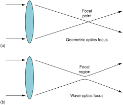
Any beam of light having a finite diameter and a wavelength exhibits diffraction spreading. The beam spreads out with an angle given by the equation . Take for
 Resolution limits for wave equation imaging
Formulas are derived for the resolution limits of migration-data kernels associated with diving waves primary reflections
 Empower System Suitability Quick Reference Guide
Warning Limit (UWL) are calculated by these formulas: Theoretically the peak width used in the Resolution formula should be the width of the peak at baseline ...
 〈621〉CHROMATOGRAPHY
applications of a reference solution and is calculated using the following equation. matrix
 RESOLUTION MSC.429(98)/REV.1 (adopted on 11 November 2020
11 nov. 2020 may be used within the allowable range/heel limits for calculation purposes. Different stages of flooding may not be combined in a single GZ ...
 Resolution limit in opto-digital systems revisited
6 jan. 2023 The utility of proposed formula is contrasted experimentally. 2. PSF of opto-digital imaging systems. The spatial resolution of a modern imaging ...
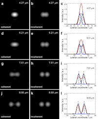
 Lateral and axial resolution criteria in incoherent and coherent
paper in which the lateral resolution limit was provided in form of an equation [5]:. Abbe. Lateral max. . 2 sin. 2NA. R n λ λ. ϑ. = = (2) where max. sinϑ is
 Resolution limits for wave equation imaging
Formulas are derived for the resolution limits of migration-data kernels associated with diving waves primary reflections
 On Tackling the Limits of Resolution in SAT Solving ?
(Boolean) Satisfiability (SAT) is the decision problem for propositional formulas i.e. to decide whether a given propositional formula is satisfiable. Since
 Resolution formulas and near-resolution-limit images of a periodic
18 ago. 2022 Abbe's formulas on the resolution limit of a one-dimensional (1D) grating pmin ¼ ??NA for on- axis illumination and pmin ¼ 0.5 ??NA for ...
 Lateral and axial resolution criteria in incoherent and coherent
on the resolution limit of an optical microscope. In this paper Abbe did not provide any mathematical equations
 Chapter 7 Lenses
formula for resolution is D = 1.22?/??condenser + NAobjective. structures far below the resolution limit of the microscope. Diffraction.
 Automated formulation and resolution of limit analysis problems
12 oct. 2020 The numerical resolution of the corresponding optimization problem is carried out by the interior-point solver Mosek which takes advantage of ...
 Resolution limits for crosswell migration and traveltime tomography
These formulas are used to estimate the limits of spatial resolution in reflection migration images and traveltime tomograms. In particular.
 Automated formulation and resolution of limit analysis problems
This paper is accompanied by a FEniCS toolbox implementing the above-mentioned framework. Keywords: limit analysis yield design
 A general theory of far-field optical microscopy image formation and
cal resolution formula d = ?/2NA. This resolution limit corresponds to a frequency cut-off of 2NA/?
 ?????????????????? ???????
formulate rules of resolution limit calculation for all types of laser microscopes that known formula for the optical resolution d = ?/?NA
Resolution limits for wave equation imaging
Yunsong Huang⁎,GerardT.Schuster
Earth Science and Engineering, KAUST, Thuwal, Saudi Arabia abstractarticle infoArticle history:
Received 3 March 2014
Accepted 26 May 2014
Available online 4 June 2014
Keywords:
Wave scattering
Wave diffraction
Computational seismology
Tomography
Migration
Formulas are derived for the resolution limits of migration-data kernels associated with diving waves, primary
reflections,diffractions,andmultiplereflections.Theyareapplicabletoimages formedby reversetimemigration
(RTM), least squares migration (LSM), and full waveform inversion (FWI), and suggest a multiscale approach to
iterative FWI based on multiscale physics. That is, at the early stages of the inversion, events that only generate
low-wavenumber resolution should be emphasized relative to the high-wavenumber resolution events. As the
iterations proceed, the higher-resolution events should be emphasized. The formulas also suggest that inverting
in theprimaries. Finally, diffractionscan provide twice or better the resolution than specularreflections for com-
parable depths of the reflector and diffractor. The width of the diffraction-transmission wavepath is approxi-
matelyλat the diffractor location for the diffraction-transmission wavepath. © 2014 Elsevier B.V. All rights reserved.1. Introduction FWI ( Lailly, 1984; Tarantola, 1984, 2005), RTM (Baysal et al., 1983; McMechan, 1983; Whitmore, 1983), LSM (Dai et al., 2012; Duquet et al., 2000; Nemeth et al., 1999; Tang, 2009) and wave-equation traveltime inversion (De Hoop and van Der Hilst, 2005; Luo, 1991; Luo tion (Krebs et al., 2009; Mora, 1988, 1989; Pica et al., 1990; Pratt and Goulty, 1991; Shin and Cha, 2008; Virieux and Operto, 2009; Zhou et al., 1995) and earthquake (De Hoop and van Der Hilst, 2005; Fichtner, 2011; Fichtner and Trampert, 2011a,b; Fichtner et al., 2009; Marquering et al., 1999; Tape et al., 2009; Tong et al., 1998; Van Der Hilst and Maarten, 2005) scales. In all of the above methods, the wave equation is inverted to estimate the model that minimizes, in some sense, the difference between the predicted and observed data. The main value of these wave equation-based imaging methods is that they overcome the high-frequency assumption of ray-based methods and use many, if not all, of the arrivals to reconstruct afinely detailed earth model. The hope is tofind models with spatial resolution of one- half wavelength, and perhaps even better if evanescent energy can beexploited (de Fornel, 2001; Fink, 2008; Schuster et al., 2012). Themain limitations of wave equation imaging are computational cost
and extensive preprocessing of the data, compared to the ray-based methods. To optimize theuse of wave equation imagingone must understand its limits of spatial resolution. Without this understanding, models can be over parameterized and lead to solutions that honor the data but violate the wavelength-based resolution limits of wave propagation. Inthelast30 years,therehasbeenmuchprogressinmathematically defining the resolution limits of seismic images. The two most impor- tant categories of seismic imaging and their resolution limits are for traveltime tomography and reflection imaging.1.1. Resolution limits for traveltime tomography
theraypaththat connects thesourceatswiththereceiver atg, whereas infinite-frequency travel time tomography, velocity updates can be confined to thefirst Fresnel zone for the specified source-receiver pair (Harlan, 1990). He states,"band-limited waves can follow paths that are not Fermatraypathsand stillcover thedistance between two points half a wavelength will add constructively to thefirst arrival." As an example, the raypaths and Fresnel zones for reflection and transmission arrivals are illustrated inFig 1. A pointxis in the FZ if and only if it satisfies the following condition (Cerveny and Soares,1992; Kravtsov and Orlov, 1990):jτ
sx xg sgJournal of Applied Geophysics 107 (2014) 137-148
Abbreviations:LSM, least squares migration;FWI,full waveforminversion; FZ,Fresnel zone; MVA, migration velocity analysis; RTM, reverse time migration.6900. Tel.: +966 128080296.
E-mail addresses:yunsong.huang@kaust.edu.sa(Y. Huang), gerard.schuster@kaust.edu.sa(G.T. Schuster).http://dx.doi.org/10.1016/j.jappgeo.2014.05.0180926-9851/© 2014 Elsevier B.V. All rights reserved.
Contents lists available atScienceDirect
Journal of Applied Geophysics
journal homepage: www.elsevier.com/locate/jappgeo where,Tis the dominant period of the source wavelet,τ sx is the traveltime for a particular type of wave to propagate fromsto the trial image point atx,andτ sg is the traveltime to propagate fromsto the specified geophone atg. In a homogeneous medium, the maximum width of thefirst Fresnel Lis the source-receiver distance andλis the dominant wavelength. Thus, widening the distance between the source and receiver lowers the spatial resolution of the traveltime tomogram. More generally, Appendix Aderives the formula for the length between any two points on opposite sides of the ellipse, which provides the horizontal resolu- tion limit for any orientation of the ellipse. In addition,Appendix A derives the formula for horizontal resolution in multilayered, rather than homogeneous, media. The effective spatial resolution limitsΔxandΔzof traveltime tomo- grams can be estimated (Schuster, 1996) as the minimum width and height of theintersectionoffirst Fresnel zones at the trial image point.This can be seen by assuming theL
2 traveltime misfitJ=∑ i J i , where J i denotes the traveltime misfit owing to thei th source-receiver pair, and assuming model consistency, i.e., there exists a velocity model that can explain all observed traveltime. If a part of the trial model lies furthest from the Fresnel zone prescribed by thei th source-receiver pair, thenJ i will dominate and steepest descent updates will propel this trial model point towards the center of this Fresnel zone. The rulethat the traveltime error is less thanT/2 for all source-receiverpairsdefinesanintersectionofalltheindividualFresnelzones.Asanex-
ample,Fig. 2illustrates the intersection zone for both a) reflection and b)transmission rays.Atany pointon the central raypath,the narrowest width is along the line perpendicular to this ray, which also defines the direction of best resolution. Thus,a horizontal ray gives the best vertical resolution while a vertically oriented ray provides the best horizontal reso- lution for transmission tomography, where the velocity is updated by smearing residuals along thefirst FZ (also referred to as a wavepath). As will be shown in the next section, this rule of thumb is also true for transmission wavepathsin FWI tomograms, except thewaveform residual is smeared along the associated wavepath.1.2. Resolution limits for reflection imaging
A seismic migration image is formed by taking the reflection energy arriving at timeτ sx xg and smearing (Claerbout, 1992) it along the appropriate ellipse in the model-space coordinatesx(seeFig. 3a). For several traces, the migration image inFig. 3b is formed by smearing 1 and summing the reflection energy along the appropriate ellipses in the model space. It is obvious that thenarrowest horizontal slice of the fat ellipse is for a trial image point at the far left and far right of the ellipse s g (0,0) (0,2d) d X a). Reflection and Mirror Transmission Fresnel Zones b). Ellipse for Resolution Analysis 224LX d y x a b sg c D E (L/2) 2 =a 2 -b 2 (-L/2,0) |s E| + |E g| = 2a = L + /2 F EP
Fig. 1.a) First Fresnel zonesfor the specular reflection and for the transmission arrival excited by the mirror source at (0,2d). Inthe latter case, the velocity model below the reflector (the
thickhorizontal line denoted byF) has been extended to be the mirror-reflection of the velocity model above the reflector. Colored layers denote the possibility that the velocity model is
multilayered, instead of homogeneous. In this case, although the Fresnel zone is not an ellipse, the horizontal resolution can be computed approximately involving the RMS velocityv
RMS (seeAppendix A). b) An ellipse intersected by a line segmentDE, where its lengthDE¼ 2ab b 2 cos 2θþa
2 -c 2 ??sin 2 θq b 2 cos 2θþa
2 sin 2θdefines the resolution limit (seeAppendix A).
a). Reflection Resolution Limits b). Transmission Resolution Limits g'g x z x s g zFig.2.Same asFig.1exceptthereisanadditionalsource-receiverpair.Theminimumwidthandheightoftheshadedintersectionzonedefine,respectively,theeffectivehorizontalΔxand
verticalΔzresolution limits of the traveltime tomogram at 1 The seismic amplitude is smeared over the thick ellipse shown inFig. 3a, where the periodTof the trace's source wavelet determines the thickness of the fat ellipse in (x,z)space;Fig. 3b illustrates that the minimum thickness of the fat ellipse as 0.5λ.138Y. Huang, G.T. Schuster / Journal of Applied Geophysics 107 (2014) 137-148
to give the best horizontal resolution in the reflection migration image.We also see that the narrowest vertical slice is directly beneath the midpoint of the source-receiver pair to give the best vertical resolution. For post-stack data, these resolution limits are given on the right side ofFig. 4e, which say that the far-offset (near-offset) trace from a trial image point gives the best horizontal (vertical) resolution. The resolution limits for migration (Berkhout, 1984; Chen and Schuster, 1999; Safar, 1985; Vermeer, 1997) are equivalent to those for linearized inversion in a homogeneous (Devaney, 1984; Wu and Toksoz, 1987) and an inhomogeneous medium (Beylkin, 1985) with smooth velocity variations. The key idea is that the model wavenumber vectorkcan be equated to the sum of the source-scatterer and geo- phone-scatterer wavenumbersk¼k sro þk gro shown inFig. 5.IfDdefines the range of wavenumbers available from the source-receiver of the migration image are defined asΔx¼min
D 2π k x¼min
D 2π k sx o þk gx o ;Δz¼min D 2π k z¼min
D 2π k sz o þk gz oð2Þ
In the far-field approximation, these limits are given inFig. 4e for post-stack migration. The above resolution analysis has been developed for migration and traveltimetomography. Until now, there has notbeena comprehensive treatmentof theresolutionlimits associated withLSM. Wenowpresent gs zt reflector somewhere in this regionSmeared
eventsG(g|s)
a) One-trace migration. reflector somewhere in this regionG(g'|g)
b) Two-trace migration. Migration: Smear and Sum Reflection Amplitude Along Ellipses g' t gsin b) has better spatial resolution than migrating just one trace in a), and the minimum thickness of each fat ellipse is 0.5λ, whereTis the dominant period of the source wavelet.
Diving Wave
/(4 )xZ X Z X L/2 2r 2 rWavepath Resolution Limit
2zX 2rL 2rL 2/2rLData Kernel Migration Kernel
Reflection
Reflection
Diffraction
Reflector
dir dir (|) (|)GGys gy rfl dir (|) (|)GGys gy dir rfl (|) (|)GGys gy dff dir (|) (|)GGys gy dir rfl (|) (|)GGys gy dir dir * [(|) (|)]GGxs gx rfl dir * [(|) (|)]GGxs gx dir rfl * [(|) (|)]GGxs gx dff dir * [(|) (|)]GGxs gx dir dir * [(|) (|)]GGxs gx a). b). c). d). e). /4zFig. 4.Migration-data kernels, associated wavepaths, and approximate resolution limits along the middle of the wavepaths for (a-d). Here, the dashed lines in thefirst column represent
are representedby; thediffractor in(d) isdenotedby ; and the resolution limit perpendicular to thewavepath isdenoted by2Δr. The resolution limits forreflection migration in(e)are
for post-stack data, whereXcorresponds to aperture width, andΔxandΔzcorrespond to the skinniest width and thickness of the fat migration ellipse.139Y. Huang, G.T. Schuster / Journal of Applied Geophysics 107 (2014) 137-148
such an analysis by applying an asymptotic analysis to the model reso- better understand and optimize the resolution characteristics of FWI,LSM, and RTM.
This paper is divided into three parts. The introduction heuristi- cally explains how wavepaths are used to estimate resolution for both traveltime tomography and migration. This leads to an intuitive description of spatial resolution as the minimum width and height of the intersection of Fresnel zones at the trial image point. The next part validates this heuristic definition by rigorously deriving the res- olution limits for each type of wavepath, and explains their relation- ship to the acquisition geometry. Finally, a discussion and summary are given.2. Born forward and adjoint modeling
The model resolution functionL
Lis a product of forwardLand ad-
jointL modeling operators under the Born approximation (Stolt and Benson, 1986). We now define the equations for these modeling operators.2.1. Born forward modeling
by a geophone atgis given by the Born modeling equation:δdgðjsÞ¼ω
2 ZGgjxðÞδmxðÞGxjsðÞdx
2 →δd¼Lδm;ð3Þ whereG(g|x) is the Helmholtz Green's function for the background velocity model, the model function perturbed from the background model is given byδm(x)=2δs(x)s(x)→δm,s(x) is the background slowness model,δs(x) is the perturbation of the slownessfield, andω is the angular frequency. For notational economy, this equation can be represented in operator notation byδd=Lδm, whereδdrepresents the scattered seismicfieldδd(g|s) under the weak scattering approxi- points in the model region. The integration in Eq.(3)is over the entire model space, but if the trace is windowed about a specific eventthentheintegrationcanbeap-proximated by that over the event'sfirst Fresnel zone associated withthe specificsource-receiver pair. For example, if the trace only contains
thetransmitted arrival, thenΩ=Ω trans. defines the points in the yellow colored wavepath inFig. 4a of the diving wave'sfirst Fresnel zone; only velocity perturbations in this zone will significantly affect the character of the diving wave arrival in the trace.2.2. Born adjoint modeling
Eq.(3)can be inverted by the iterative steepest descent formulaδmxðÞ
kþ1¼δmxðÞ
k -αδmxðÞ mig ;ð4Þ where the misfitgradientδm(x) mig is given by the Born adjoint model- ing equationδmxðÞ
mig 2 Z DGgjxðÞ
GxjsðÞ
δdgjsðÞdx
g dx s →δm mig ¼Lδd;ð5Þ
and the integration of points inDis over the range of the horizontal source and receiver coordinates along the horizontal recording line atz= 0. Here,δd(g|s)=d(g|s)-d(g|s) obs ,L represents the adjoint of the modeling operatorL, the step length is denoted byα,d(g|s)is the trace predicted from the estimated slowness model, and the ob- served trace is represented byd(g|s) obs .Themisfitgradientsymbolδm(x)
mig is superscripted bymigbecause it also represents the migration of the residual. In fact, thefirst iterationk= 0 of Eq.(5)rep- resents the reverse time migration of the scattered data recorded at the surface. If the windowed event is the reflection, Eq.(5)says that the velocity model is updated by smearing the residual 2 along the yellow colored rabbit ears 3 inFig. 4b-c and the yellow ellipse inFig. 4e. Smearing resid- uals along the rabbit ears (ellipse) with the b-c (e) migration kernel ity model (Liu et al., 2011; Mora, 1989; Zhou et al., 1995). The spatial resolution limitsΔxandΔzassociated with any point along the central rays are determined by the, respectively, horizontal and vertical widths of thefirst Fresnel zone.3. Model resolution function and FWI resolution limits
In theIntroduction, the model resolution limits were defined for traveltime transmission tomography and reflection migration, where λis considered as the dominant wavelength. For a band-limited source wavelet, the dominant wavelength is typically associated with the peak frequency. Now the model resolution limits will be derived for FWI by applying asymptotic analysis to the model resolution function that relates the modelδmto the reconstructed imageδm mig . Note in passing that in practice, FWI is typically carried out in multiscale (Bunks et al.,1995; Sirgue and Pratt, 2004) such that at a given stage, FWI only con-
cerns the source waveletfiltered into a narrowband. In this case, the per- tinentλstill belongs to the peak frequency of the narrowband source. In Because the inversion process of LSM tends to deconvolve the source wavelet, the resolution limits are defined asymptotically by theλasso- ciated with the upper cutoff frequency of the source wavelet. 2 The residual can be either the traveltime residual or the waveform residual. 3 There are two steps for creating an upgoing reflection wavepath:first, generate the fromthe sourcetothereflector.Then,fireoffthese explodingreflectorstoget theupgoing reflectionfieldsU(x,t). The upgoing rabbit ear wavepath is computed by taking the zero- lag correlation betweenU(x,t) and the backpropagated dataB(x,t). s gModel Wavenumber k for
Diffraction Migration
90-φ
central ray r o =(x,z) k grquotesdbs_dbs47.pdfusesText_47[PDF] Limitation de l'intensité: le coupe-circuit
[PDF] limitation de vitesse allemagne
[PDF] limitation de vitesse autoroute france
[PDF] limitation de vitesse en agglomération
[PDF] limitation de vitesse hors agglomération
[PDF] limitation de vitesse la plus élevé
[PDF] limitation de vitesse usa
[PDF] Limitation des risques de contamination et d'infection
[PDF] limitationde l'intensité:le coupe circuit
[PDF] Limite
[PDF] limite 0/infini
[PDF] limite calcul
[PDF] limite conventionnelle d'élasticité
[PDF] limite cosinus
 Understanding Resolution