 Powerwall 2 AC Installation Manual
Figure 11: Single Phase Wiring. Example Using RCD Main Switch. Design Considerations If the site has a 3-phase electrical system complete the test on L1 ...
 eaton-rcd-application-guide-br019003en-en-us.pdf
11 Wiring diagram of RCD functionally dependent on supply voltage (VI). 1 conductors N and PE
 Operation & Installation Manual
Wiring Overview Diagram When enabled all readings from 3-phase myenergi devices configured as 3-phase
 Surge Installation Guide
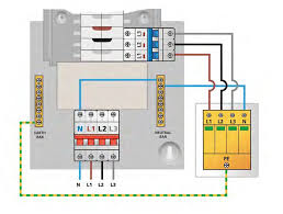
BS 7671: The 18th Edition Wiring Regulations Please also note that for a three phase supply a three phase SPD will need to be installed across all three ...
 schneider-wiring-diagram-book.pdf
FIBER OPTIC. TRANSCEIVER. CLASS 9005 TYPE FT. FIBER OPTIC. PUSH BUTTON. SELECTOR SWITCH
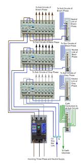
 Wiring of Three Phase Distribution Board/Consumer Unit Installation
electrical lighting fixtures etc. ... The Practical Way of Wiring the Three Phase 60A Distribution Board with a. MCCB. Wiring Diagram according to Old Colour Code ...
 Three Phase System
pdf; installing without confirmation may void the inverter warranty. For more wiring information refer to the SolarEdge Recommended AC Wiring. Application Note
 Electrical Symbols Guide.pdf
Common Schematic Drawing Symbols. Switch. Switch- fuse. Fuse-switch. Isolator Three-phase winding - Star. Changer general symbol. Converter
 Megger-Guide-to-Insulation-Testing.pdf
If the apparatus you are testing has very small capacitance such as a short run of house wiring
 Wiring Unlimited
Parallel and/or 3-phase system DC wiring . ... If you construct an electrical diagram of an incorrectly wired battery bank it will look like this:.
 Trade of Electrician Three-phase Distribution Boards And Socket
Most electrical equipment in industrial premises operate on a three-phase supply. This layout shows the Lighting Power and Heating loads separated from ...
 Three-Phase Wiring Diagrams
Three-Phase Wiring Diagrams. ALWAYS USE WIRING DIAGRAM SUPPLIED ON MOTOR NAMEPLATE. - colored leads are only applicable on the NEW ROLLED STEEL motor lines
 Wiring Diagram Book
Wiring Diagrams. 55-57. Type S AC Combination Magnetic Starters ......... 58-59. Class 8538 and 8539. 58-59. 3-Phase Size 0-5. 58. 3-Phase Additions and ...
 GENERAL SPECIFICATIONS FOR ELECTRICAL WORKS
(iii) All circuits shall be indicated and numbered in the wiring diagram and (v) Three phase DBs shall not be used for final circuit distribution as far ...
 BASIC CONCEPT OF HOUSE WIRING
House Wiring (Single Phase) Wiring Diagram 3x22 SWG means 3 wire copper each of 22 Gauge covered with PVC insulation.
 ELECTRICTY WIRING CODE 2018.pdf
Oct 16 2016 2.5 Standard Electrical diagram symbols: Symbol. Description. Symbol. Description. Main Distribution Board (MDB). Three phase isolator.
 Wiring Unlimited - Rev 07 1
6.7 Special considerations for AC wiring of parallel and/or 3 phase inverter/chargers . If you construct an electrical diagram it will look like this:.
 INSTALLATION MANUAL
Typical Field Control Wiring Diagram For Air Conditioner Models . . . 6 A filter rack kit is included with all three phase units.
 Queensland Electricity Metering Manual
Aug 24 2018 Where it is known that a single tariff two or three-phase supply will be required at ... accordance with the wiring diagrams in this manual.
 Powerwall 2 AC Installation Manual
Backup Gateway 2 Electrical Specifications. Maximum Overcurrent. Protection Device. 100 A. (single-phase service). 80 A. (2- and 3-phase service).
Wiring Diagram Book
A1 15B1 B2 16 18B3 A2B1 B3
15 16 18Supply voltage
L M H2 LevelsB2
L1 FU1 460 VFU2
GNDL3L2H1 H3 H2 H4
F U 3 X1A F U 4F U 5 X2A R Power OnOptional115 V
X1 X2230 V
H1 H3 H2 H4
Optional Connection
Electrostatically
Shielded Transformer
F U 6 OFF ON M L1 L2 2 1OLSTOPMSTART
3 START STARTSTOPSTOP
FIBER OPTIC
TRANSCEIVER
CLASS 9005 TYPE FTFIBER OPTIC
PUSH BUTTON,
SELECTOR SWITCH,
LIMIT SWITCH, ETC.
FIBER OPTIC CABLE
ELECTRICAL
CONNECTIONS
BOUNDARY SEAL TO BE IN
ACCORDANCE WITH ARTICLE
501-5 OF THE NATIONAL
ELECTRICAL CODE
HAZARDOUS LOCATIONS NONHAZARDOUS LOCATIONS
CLASS I GROUPS A, B, C & D
CLASS II GROUPS E, F & G
CLASS III
FIBER OPTIC CABLEL1 L2 L3135
A1 A2T1 T2 T3
246OR DISCONNECT SWITCH
L1 L2 L3CIRCUIT BREAKER
START STOP M OT T1 T2 T3 M MSOLID STATE
OVERLOAD RELAY
1CT M M MOTOR 3CTTO 120 V
SEPARATE
CONTROL
OT is a switch that opens
when an overtemperature condition exists (Type MFO and MGO only) T1T3MOTOR3
2 L2 T2L3 T3 T2 L1 1 T1 13144344535431322122
Status
(N.O. or N.C.)Location A1 15B1 B2 16 18B3 A2B1 B3
1516 18Supply voltage
L M H2 LevelsB2
2122
13 14 X1X3 AC L1 L2 LOAD
Orange
X2 Green AC 15 9 2 6 10 481214 (+)
13 (-)
A1/+ 15 25 Z1 Z2
16 18 A2/-V
s 26 28A1 A2
File 0140
© 1993 Square D. All rights reserved. This document may not be copied in whole or in part, or trans-
ferred to any other media, without the written permission of Square D. Electrical equipment should be serviced only by qualified electrical maintenance personnel, and this document should not be viewed as sufficient instruction for those who are not otherwise qualified tooperate, service or maintain the equipment discussed. Although reasonable care has been taken to pro-
vide accurate and authoritative information in this document, no responsibility is assumed by Square D for any consequences arising out of the use of this material.COPYRIGHT NOTICE
PLEASE NOTE:
QWIK-STOP
and ALHPA-PAK are registered trademarks of Square D. NEC is a registered trademark of the National Fire Protection Association.TRADEMARKS
Table of Contents
i Standard Elementary Diagram Symbols.....................1-3 NEMA and IEC Markings and Schematic Diagrams......4Control and Power Connection Table 4
Examples of Control Circuits..........................................62-Wire Control 6
3-Wire Control 6-9
Shunting Thermal Units During Starting Period 10
Overcurrent Protection for 3-Wire Control Circuits 11AC Manual Starters and Manual Motor
Starting Switches ...........................................................12Class 2510 12
Class 2511 and 2512 13
2-Speed AC Manual Starters and
IEC Motor Protectors......................................................14Class 2512 and 2520 14
GV1/GV3 14
Drum Switches................................................................15Class 2601 15
DC Starters, Constant and Adjustable Speed..............16Class 7135 and 7136 16
Reversing DC Starters, Constant and
Adjustable Speed ...........................................................17Class 7145 and 7146 17
Mechanically Latched Contactors ................................18Class 8196 18
Medium Voltage Motor Controllers..........................18-25Class 8198 18-25
Solid State Protective Relays...................................26-27Class 8430 26-27
General Purpose Relays................................................28Class 8501 28
NEMA Control Relays.....................................................29Class 8501 and 9999 29
General Purpose Relays................................................30Class 8501 30
Sensing Relays...............................................................30RM2 LA1/LG1 30
IEC Relays..................................................................31-32IEC D-Line Control Relays 31
Class 8501 32
Type P Contactors.....................................................33-35Class 8502 33-35
Class 8702 35
Type T Overload Relays............................................33-35Class 9065 33-35
Type S AC Magnetic Contactors..............................36-40Class 8502 36-40
IEC Contactors ..........................................................41-42IEC Contactors and Auxiliary Contact Blocks 41
Input Modules and Reversing Contactors 42
Type S AC Magnetic Starters ...................................43-50Class 8536 43-50
8538 and 8539 45,49
1-Phase, Size 00 to 3 43
2-Phase and 3-Phase, Size 00 to 5 44
3-Phase, Size 6 45
3-Phase, Size 7 46
3-Phase Additions and Special Features 47-50
Integral Self-Protected Starters ...............................51-57Integral 18 State of Auxiliary Contacts 51-52
Integral 32 and 63 State of Auxiliary Contacts 53-54Wiring Diagrams 55-57
Type S AC Combination Magnetic Starters ............58-59Class 8538 and 8539 58-59
3-Phase, Size 0-5 58
3-Phase Additions and Special Features 59
Reduced Voltage Controllers...................................60-66Class 8606 Autotransformer Type 60-61
Class 8630 Wye-Delta Type 62-63
Class 8640 2-Step Part-Winding Type 64
Class 8647 Primary-Resistor Type 65
Class 8650 and 8651 Wound-Rotor Type 66
Solid State Reduced Voltage Starters..........................67Class 8660 ALPHA PAK
, Type MD-MG 67 Solid State Reduced Voltage Controllers ...............68-70Class 8660 Type MH, MJ, MK and MM 68-70
Table of Contents
iiType S AC Reversing Magnetic Starters71-72
Class 873671-72
2- and 3-Pole71
3- and 4-Pole72
Type S AC 2-Speed Magnetic Starters73-76
Class 881073-76
Special Control Circuits75-76
Multispeed Motor Connections76-77
1- Phase76
3-Phase76-77
Programmable Lighting Controllers78
Class 886578
AC Lighting Contactors79-81
Class 890379-81
Load Connections79
Control Circuit Connections80
Panelboard Type Wiring81
Electronic Motor Brakes81-82
Class 8922 QWIK-STOP
81-82Duplex Motor Controllers82
Class 894182
Fiber Optic Transceivers82
Class 900582
Photoelectric and Inductive Proximity Switches83
Class 900683
Photoelectric and Proximity Sensors84-89
XS, XSC, XSF and XSD84
XS and XTA85
SG, ST and XUB86
XUM, XUH, XUG, XUL and XUJ87
XUE, XUR, XUD, XUG and XUE S88
XUV89Limit Switches and Safety Interlocks90-92
Class 900791
XCK and MS92
Pressure Switches and Transducers93
Class 9012, 9013, 9022 and 902593
Level Sensors and Electric Alternators94
Class 9034 and 903994
Pneumatic Timing Relays and Solid State
Industrial Timing Relays95-96
Class 905095-96
Timers97
Class 905097
Transformer Disconnects98
Class 907098
Enclosure Selection Guide99
Conductor Ampacity and Conduit Tables100-101
Wire Data102
Electrical Formulas103-104
List of Tables
quotesdbs_dbs12.pdfusesText_18[PDF] 3 sulfolene and maleic anhydride reaction
[PDF] 3 theories of language acquisition pdf
[PDF] 3 tier architecture advantages and disadvantages
[PDF] 3 tier architecture client server model
[PDF] 3 tier architecture diagram c#
[PDF] 3 tier architecture diagram in asp.net
[PDF] 3 tier architecture example in asp.net with c#
[PDF] 3 tier architecture in .net
[PDF] 3 tier architecture in advanced java
[PDF] 3 tier architecture model
[PDF] 3 tier architecture of mobile computing
[PDF] 3 tier architecture project in c#.net
[PDF] 3 tier math model intervention
[PDF] 3 tier model speech and language therapy
