 Create a Simple Network Using Packet Tracer - Cisco Community
Here type the name “HomeNetwork” as shown in the figure. Configure the Internet connection on the wireless router. Click on the Setup tab in the wireless
 CSC 435 Computer Networks Spring 2019 Instructor: Dr. Natarajan
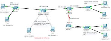
Project # 5: Simulation using Cisco Packet Tracer. Linksys Wireless Router sample ones used in the network layout). Network Layout (the IP addresses and ...
 Andrea Finardi - IoT Simulations with Cisco Packet Tracer
4 июн. 2018 г. In each of the four simulations there is one example of sensor-to-actuator cases using basic Blockly programming of the microcontroller devices.
 Final Project Report
20 июн. 2013 г. Cisco 7200 router with IOS 12.3(22) ... different packets in each router making that sample unusable for the latency.
 IoT Projects in Packet Tracer
(Fan and Light in this example) with smart phone. 11.3 Smart Things and Sensors Figure 11.12 Adding sensors in Cisco Packet Tracer. Figure 11.13 Adding ...
 Teaching Innovation in Computer Network Course for
A tool named. Packet Tracer from Cisco network academy has been adopted in our classes since 2007. Practical exercises [6] and projects help students to
 INTERNET OF THINGS SIMULATION USING CISCO PACKET
The tool used is Cisco packet tracer which is a software developed by Cisco that is used to create and simulate a virtual network basically a wireless network
 Packet Tracer Guide - Digital and IT Skills Sector
programme and only need access to Cisco Packet Tracer and how to use it
 Nexus 9000: Packet Tracer tool explained - Cisco
N9K-9508#test packet-tracer show <==== Check for packet matches. The above commands programs the trigger on every Broadcom Trident II Asic that exist on the.
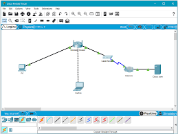
 Create a Simple Network Using Packet Tracer - Cisco Community
Packet Tracer should open with a blank default. Logical topology workspace as shown in the figure. Step 2: Build the topology a. Add network devices to the
 Andrea Finardi - IoT Simulations with Cisco Packet Tracer
04-Jun-2018 In each of the four simulations there is one example of sensor-to-actuator cases using basic Blockly programming of the microcontroller devices.
 Configuring a Simple Firewall - Cisco
router also supports packet inspection and dynamic temporary access lists by In the configuration example that follows the firewall is applied to the ...
 Cisco Packet Tracer Data Sheet
Within this framework the Cisco® Packet Tracer e-learning software was developed to help Networking Academy students gain practical networking technology
 College Network Scenario Implementation by using Cisco Packet
Abstract: Different users are there for the project; the users are present The network simulator that is Cisco Packet Tracer is a straightforward easy ...
 ADVANCED LEVEL CAMPUS NETWORKING DESIGNING ON
This project is about designing of computer network for CAN on simulation software GNS3 or Cisco packet tracer. CAN stands for. Campus Area Network. This study
 Design and Simulation of Local Area Network Using Cisco Packet
27-Oct-2017 Cisco Packet Tracer (CPT) is a multi-tasking network simulation software ... written in dotted-decimal notation for example 192.168.23.100.
 Becoming A Cisco Networking Academy Frequently Asked Questions
Beyond Packet Tracer the practice labs can leverage capabilities within a student laptop/desktop and a generic wireless home router. (Equipment example may
 LAB MANUAL for Computer Network
For example if you Apparatus (Software): Command Prompt And Packet Tracer. ... From global configuration mode
 Basic Router Configuration – Cisco
In the following configuration example the static route sends out all IP packets with a destination IP address of 192.168.1.0 and a subnet mask of 255.255.
 The International Journal of Engineering and Science (IJES) || Volume || 6 || Issue || 10 || Pages || PP 63- 77 || 2017 ||
 ISSN (e): 2319 1813 ISSN (p): 2319 1805
DOI: 10.9790/1813-0610026377 www.theijes.com Page 63
Design and Simulation of Local Area Network Using Cisco PacketTracer
Nathaniel S. Tarkaa1, Paul I. Iannah2, Isaac T. Iber31 2 3Department of Electrical and Electronics Engineering, University of Agriculture, Makurdi, Nigeria
Corresponding author: Nathaniel S. Tarkaa
Computer networks have become extremely important in our present-day society. A majority of companies
depend on the proper functioning of their networks for communications, administration, automation, e-business
solutions, etc. The Local Area Network (LAN) is the most basic and important computer network owned by
individual companies and could be used for interconnection with wide area networks. A LAN permits effective
cost sharing of high-value data processing equipment such as mass storage media, mainframe computers or
minicomputers, and high-speed printers. Resource sharing is probably equally as important where a LAN
serves as the access vehicle for an intranet or the Internet. In view of this, system managers need professional
tools to help them with the design and maintenance of LANs. A simulation tool offers a way to predict the
impact on the network of a hardware upgrade, a change in topology, an increase in traffic load or the use of a
new application. So in this paper, a LAN network is designed using Cisco Packet Tracer. The paper describes
how the tool can be used to develop a simulation model of the LAN for the College of Engineering of the
University of Agriculture, Makurdi, Nigeria. The study provides an insight into various concepts such as
topology design, IP address configuration and how to send information in form of packets in a single network
and the use of Virtual Local Area Networks (VLANs) to separate the traffic generated by different departments.
Keywords: Computer Networks, IP Addresses, Ping Test, Simulation Tool, Subnetting, VLANsDate of Submission: 06-10-2017 Date of Publication: 27-10-2017
I. INTRODUCTION
The need for computer networking was borne out of the need to use personal computers for sharinginformation within an organization in form of messages, sharing files and data bases and so forth. Whether the
organization is located in one building or spread over a large campus, the need for networking the computers
cannot be over emphasized. As the name implies, a Local Area Network (LAN) interconnects computers in a
limited geographic area. It provides high-bandwidth communication over inexpensive transmission media [1].
The corporate LAN has evolved from a passive background business component to a highly active, visible core
asset that enterprises rely on to support day-to-a strategic instrument that must be accessible anytime from anywhere-simultaneously offering fast, secure,
reliable services at scale regardless of location [2]. The main purpose of a network is to reduce isolated users and
workgroups. All systems should be capable of communicating with others and should provide desired
information. Additionally, physical systems and devices should be able to maintain and provide satisfactory
performance, reliability and security. Resource sharing is probably equally of immense importance where a LAN
serves as the access vehicle for an intranet or the Internet [2]. In view of this, system managers need professional
tools to help them with the design and maintenance of LANs [3]. A simulation tool offers a way to predict the
impact on the network of a hardware upgrade, a change in topology, an increase in traffic load or the use of a
new application. So in this paper, a LAN network is designed using Cisco Packet Tracer. Cisco Packet Tracer (CPT) is a multi-tasking network simulation software that can be used to performand analyze various network activities such as implementation of different topologies, selection of optimum path
based on various routing algorithms, creation of appropriate servers, subnetting, and analysis of various network
configuration and troubleshooting commands [4]. In order to start communication between end user devices and
to design a network, we need to select appropriate networking devices like routers, switches, hubs and make
physical connection by connecting cables to serial and fast Ethernet ports from the component list of packet
tracer [4]. Networking devices are costly so it is better to perform first on packet tracer to understand the concept
and behavior of the network [4]. The paper describes how the CPT tool can be used to develop a simulation model of the LAN for theCollege of Engineering of the University of Agriculture, Makurdi, Nigeria. The study provides an insight into
Design and Simulation of Local Area Network Using Cisco Packet TracerDOI: 10.9790/1813-0610026377 www.theijes.com Page 64
various concepts such as topology design, IP address configuration and how to send information in form of
packet in a single network and the use of Virtual Local Area Networks (VLANs) to separate the traffic generated
by the different departments. VLANs are a new type of LAN architecture using intelligent, high-speed switches
[5]. The simulation results and performance analyses showed that the design was successful.The rest of the paper is organized as follows: Section 2 discusses the different LAN topologies. This is
followed by a discussion in section 3 on the different types of transmission media. VLANs are discussed in
section 4. The concept of IPv4 addressing and subnetting is presented in section 5. In section 6, the development
Lastly in section 8 is the conclusion.
II. NETWORK TOPOLOGY
According to [4], for interconnectivity of components, network topology describe the physical andlogical appearance and interconnection between arrangement of computers, cables and other components in a
data communication network and how it can be used for taking a packet from one device and sending it through
the network to another device on a different network. A network topology is the physical layout of computers,
cables, and other components on a network. There are a number of different network topologies, and a network
may be built using multiple topologies. The different types of network topologies are: Bus topology, Star
topology, Mesh topology, Ring topology, Hybrid topology and Wireless topology.The bus topology typically uses a cable running through the area requiring connectivity. Devices that
need to connect to the network then tap into this nearby cable. To prevent signal bounce, a terminator is
designed to absorb the signal when the signal reaches the end. The Star Topology is a network topology in which all the clients or machines on the network areconnected through a central device known as a hub or switch. Each workstation has a cable that goes from the
network card to the hub or switch device. One of the major benefits of the star topology is that a break in the
cable causes only the workstation that is connected to the cable to go down, not the entire network as it is with
the bus topology. In a mesh topology, every workstation has a connection to every other machine or workstation on the network. the cost of implementation.In a ring topology, all computers are connected via a cable that loops in a ring or circle. A ring topology
is a circle that has no start and no end. Signals travel in one direction on a ring while they are passed from one
computer to the next, with each computer regenerating the signal so that it may travel the distance required.
Some networks of today are implemented by having a combination of more than one topology: star and bus, star
and ring, ring and bus or ring, bus and star. Networks implemented in this way are said to be hybrids.
A wireless topology is one in which few cables are used to connect systems. The network is made up of
transmitters that broadcast the packets using radio frequencies. The network contains special transmitters called
wireless access points which extend a radio sphere in the shape of a bubble around the transmitter. Wireless
topology can either be an ad-hoc or an infrastructure based implementation [6].III. COMMUNICATION MEDIA
Network devices are connected together using a medium, the medium can be cables which can either becoaxial cable or twisted pair cable or it can be by optic fiber cables or the medium can be free space (air) by the
use of radio waves. A discussion of the media is as outlined below [7]:3.1 Coaxial Cable
This cable is composed of two conductors. One of the conductors is an inner insulated conductor andthis inner insulated conductor is surrounded by another conductor. This second conductor is sometimes made of
a metallic foil or woven wire. Because the inner conductor is shielded by the metallic outer conductor, coaxial
cable is resistant to electromagnetic interference (EMI). Coaxial cables have an associated characteristic
impedance, which needs to be balanced with the device (or terminator) with which the cable connects. There are
two types of coaxial cables: Thicknet (10Base5), and Thinnet (10Base2). The two differ in thickness (1/4-inch
for thicknet and ½-inch for thinnet) and in maximum cable distance that the signal can travel (500 meters for
thicknet and 185 meters for thinnet). A transceiver is often connected directly to the ThickNet cable using a
connector known as vampire tap.3.2 Twisted Pair Cable
This is the most popular LAN media type in use today. Individual insulated copper strands are
intertwined into a twisted pair cable. Two categories/types of twisted pair cable include Shielded Twisted Pair
Design and Simulation of Local Area Network Using Cisco Packet TracerDOI: 10.9790/1813-0610026377 www.theijes.com Page 65
(STP) and Unshielded Twisted Pair (UTP). To define industry-standard pinouts and color coding for twisted-
pair cabling, the TIA/EIA-568 (Telecommunication Industry Association/Electronic Industries Alliance)
standard was developed. The first iteration of the TIA/EIA-568 standard has come to be known as the TIA/EIA-
568-A standard, which was released in 1991. In 2001, an updated standard was released, which became known
as TIA/EIA-568-B. The pinout of these two standards is the same however, the color coding of the wiring is
different. Table 1 shows the TIA/EIA-568 standard.Table I: TIA/EIA-568 Wiring Standard
Pin No. TIA/EIA-568-A TIA/EIA-568-B
quotesdbs_dbs2.pdfusesText_4[PDF] cisco packet tracer student lab manual
[PDF] cisco packet tracer tutorial for beginners pdf
[PDF] cisco packet tracer tutorial for beginners ppt
[PDF] cisco partner id
[PDF] cisco partner locator
[PDF] cisco partner program
[PDF] cisco partner ranking
[PDF] cisco partner types
[PDF] cisco password decrypt type 15
[PDF] cisco password encryption algorithm
[PDF] cisco password encryption type 4
[PDF] cisco password encryption type 5
[PDF] cisco password encryption type 6
[PDF] cisco password encryption type 8
