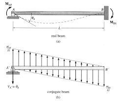
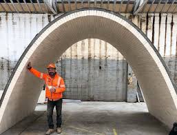
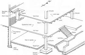
 การวิเคราะห โครงสร าง Structural Analysis
หนังสืออ างอิง. Page 7. Structural Analysis. 1-1. บทที่1. บทนํา. 1.1 บทนํา. โครงสร าง (structure) ในทางวิศวกรรมโยธาคือ สิ่งก อสร างใดๆ ที่ได จากการก อสร าง
 CTSCIVIL
Figure 1-1: Summary of structural engineering design process. Page 7. College of Theory of Structures. 25. Dr. Alshaiji ©. 2.8.1 Procedure for Analysis. The ...
 STRUCTURAL ANALYSIS Objectives: 1. To provide students the
Examination III. 6. 10. Matrix Displacement Method: Beams. 8. Approximate Analysis of Indeterminate Structures. 9
 Structural Analysis
structural analysis for the proper functioning and safety of the structure cannot structure with hybrid joints by a rigid-jointed structure is Σ(m- 1)
 Structural Analysis 1 : fundamentals of statics and strength of materials
analyse simple linear structures by means of tools from statics and materials resistance. • maintain a dialogue with an engineer specialised in this field.
 Topological Structural Analysis of Digitized Binary Images by Border
This algorithm is an extended version of the border following algorithm [l] which discriminates between outer borders and hole borders. The extensions are: (1)
 Chapter 6: Analysis of Structures
Page 1. Chapter 6: Analysis of Structures. Some of the most common structures Almost everything has an internal structure and can be thought of as a " ...
 STRUCTURAL ANALYSIS บทที่ 3 Moment Distribution
1. หาค า member stiffness factor K ของ. แต ละช วงของคาน. 4( ). K. AB. AB. AB. EI. L.
 Structural Analysis Fifth Edition
The objective of this book is to develop an understanding of the basic principles of structural analysis. 1. 2. ð800Þð20Þ. 20. 3 ! ¼ À. 116666.67 k-ft3. EI.
 An Introduction to the Structural Analysis of Narrative Roland
14 ธ.ค. 2549 Page 1. An Introduction to the Structural Analysis of Narrative. Roland Barthes; Lionel Duisit. New Literary History Vol. 6
 LECTURE NOTES ON STRUCTURAL ANALYSIS (ACE008)
1. In the beginning it is usually useful to label the members and the joints in your truss. This will help you keep everything organized and consistent in
 Structural analysis
Conventional building structures may in certain cases
 Examples in Structural Analysis
1. Structural Analysis and Design. 1. 2. Material and Section Properties. 28. 3. Pin-Jointed Frames. 76. 4. Beams. 178. 5. Rigid-Jointed Frames.
 Topological Structural Analysis of Digitized Binary Images by Border
This algorithm is an extended version of the border following algorithm [l] which discriminates between outer borders and hole borders. The extensions are: (1)
 Read PDF Structural Analysis 2 Civil Engineering Question Bank
Structural Analysis-2 - SA-2 Study Materials
 CTSCIVIL
Chapter (1): Introduction to Structural Engineering Concepts . Preliminary design approximate theories of structural analysis are used to minimize.
 Chapter 6: Analysis of Structures
In this chapter we will find the internal forces in the following types of structures : Monday
 File Type PDF Structural Analysis 2 Civil Engineering Question Bank
09-Mar-2022 Lets Crack Online Exam. Civil Engineering MCQ. PWD CPWD
 Bookmark File PDF Structural Analysis 2 Civil Engineering Question
09-Mar-2022 structural analysis – ii 1. ANALYSIS OF STATICALLY. INDETERMINATE STRUC-. TURES: Degree of static and kinematic indetermi- nacies analysis of ...
 Structural Analysis with the MICMAC Method
Within the framework proposed by Michel Godet in his scenario method (see Figure 1) this paper will present more precisely the first two families: structural
TITLE 2. STRUCTURAL ANALYSIS
CHAPTER V. STRUCTURAL ANALYSIS
Section 17. General
The structural analysis consists of obtaining the effect of actions on all or part of the structure in order to check the ultimate limit states and serviceability limit states defined in Section 8. Such an analysis must be conducted for the different design situations given in Section 7 using adequate structural models that consider the influence of all relevant variables.Section 18. Idealisation of the structure
18.1. Structural models
In order to conduct the analysis, both the geometry of the structure and the actions and support conditions are idealised by means of an adequate mathematical model, which must also roughly reflect the stiffness conditions of the cross-sections, members, joints and interaction with the ground. The structural models must allow to consider the effects of movements and deformations in those structures or part thereof, where second-order effects increase the effects of the actions significantly. In certain cases, the model must incorporate the following into its stiffness conditions: - the non-linear response of the material outside the elastic analysis; - the effects of shear lag in sections with wide flanges; - the effects of local buckling in compressed sheet panels;TITLE 2 page 1
- the effects of the catenary (using a reduced modulus of elasticity, for example) and of displacement on structures with cables; - the shear deformability of certain structural members; - the stiffness of the joints; - interaction between the ground and the structure. Where it is necessary to conduct dynamic analyses, the structural models must also consider the properties of mass, stiffness, resistance and damping of each structural member, as well as the mass of other, non-structural, members. Where it is appropriate to perform a quasi-static approximation of the structure's dynamic effects in accordance with the codes or regulations in force, such effects may be included in the static values of the actions, or dynamic amplification factors equivalent to such static actions could even be applied. In some cases (e.g. vibrations caused by wind or earthquake), the effects of the actions may be obtained from linear elastic analyses using the modal superposition method. Structural analyses for fire require specific models that are considered in Chapter XII. In some cases, the results of the structural analysis may undergo marked variations regarding to possible fluctuations in some model parameters or in the design hypotheses adopted. In such cases, the Designer shall perform a sensitivity analysis that allows to limit the probable range of fluctuations in the structural response.18.2. Member models
For purposes of the analysis, structural members are classified as one dimensional when one of the dimensions is much greater than the others, two dimensional when one of the dimensions is small in comparison with the other two, and three-dimensional when none of the dimensions is significantly greater than the others. The Designer shall in each case select the most suitable member type to show the structural response satisfactorily. The directrix of the member will usually follow the alignment of the elastic centres of mass of the cross-sections.18.2.1. Design spans
Unless especially justified, the design span of a one-dimensional member shall be the distance between the support axes or the intersection points of its directrix and those of adjacent members.18.2.2. Static shear magnitudes of cross-sections
The global structural analysis may in most cases be performed using the gross cross-sections of the members, based on their nominal dimensions. For one-dimensional members, the static magnitudes to be considered are the area, the principal moments of inertia and the uniform torsion modulus.TITLE 2 page 2
The shear area and effects of distortion on the section and warping torsion need only be taken into account in some special cases. The effects of shear lag in sections with wide flanges, and the effects of local buckling of compressed sheet panels, on member stiffness must be taken into account when these may have a significant impact on the results of the structural analysis. The effect of shear lag on flanges may be taken into account by considering effective widths, in accordance with Section 21. The effect of local buckling of compressed panels on member stiffness may be taken into account by means of equivalent effective sections in the case of slender cross-sections of class 4, in accordance with subsection 20.7. In the case of sections with principal axes that do not coincide with the planes where load is acting, the Designer must use structural models that a correct estimation of the actual response of the members subject to biaxial bending. When the shear force centre does not coincide with the centre of mass of the cross-section, mainly in open sections, the structural model must also take due account of the actions, static magnitudes and geometry of the members, so as to reproduce the effects of bending and torsion on the structure reliably, as well as any mutual interaction and load eccentricities.18.2.3. Consideration of the effects of distortion on closed section members
In members subjected to torsion, and areas where significant concentrated loads are applied, the effects resulting from deformations owing to distortion of the cross section must be considered if they are significant. In order to monitor the magnitude of such effects in large closed sections (bridge box girders, for example), it will usually be necessary to have an internal stiffness system using transverse members called diaphragms, which may be frames, triangulations or plate girders. The effects of distortion may be discounted when the actual stiffness or dimensions of the cross-section (hollow sections, for example), and/or of any diaphragms, limit the effects of the distortion, once they have been added, by less than10 % of the material's reduced yield strength in the member in question under the
relevant local or eccentric actions. Where diaphragms are necessary, they must be designed for the stresses resulting from their stiffening effect on the closed section, for the torsion actions (under eccentric loads or in members of curve directrix in plan) or when they are close to concentrated loads (intermediate and supports), according to Annex 3. In the presence of dynamic actions, the effects of distortion on the members and state.18.2.4. Consideration of the effects of mixed torsion on members with open
or closed sections The content of this subsection only applies directly to linear members subjected to torsion where the distance between points where there is no moment is equal to orTITLE 2 page 3
greater than 2.5 times its depth, and the width is less than or equal to four times its depth, and the directrix is straight or curved. The response of linear members to torsion, where the effects of distortion on the members may be discounted, is the sum of two mechanisms: a) uniform or Saint-Venant torsion that only generates shear stresses in the cross section and the stiffness of which is characterised by the torsion modulus It of the cross-section; b)non-uniform or warping torsion that generates both direct and shear stress in the different sheet panels of the cross-section. Its stiffness remains characterised by
its warping modulus, I w The response of a member to torsion may be obtained through an elastic analysis that incorporates the general equations for mixed torsion, depending on the static torsional magnitudes of the cross-sections, I t and I w , the material deformation modulus, E and G, the connecting factors for rotation and warping at the ends of the member, and the distribution of torsion action along it. Alternatively, the structural analysis for torsion may be approached through finite elements models for the part. It may be permitted for the effects of warping stress to be discounted in a suitably approximate way, to analyse just the uniform torsion in members in the following cases: a) members that have freedom to warp at their extremities and which are required solely for moment at such extremities; b) members in which the warping module of the cross-section, I w , is of negligible or small magnitude in comparison with the torsion module, I t . This is the case for the following: solid sections (round, square, rectangular, etc.); open cross-sections made up of rectangles that are sheared at a given point (angles, cross-shaped sections, single T units, etc.); closed cross-sections (tubes, single-cell or multi-cell boxes with no distortion, etc.). Additionally, by way of simplification, it may be permitted for the effects of uniform torsion to be discounted, and only analyse the warping stress, in the case of beams with thin-walled open sections such as double T, U, H, Z sections, etc. Where the static equilibrium of a structure basically depends on the torsion resistance of one or more members, such members shall mainly be designed using closed sections. In such cases, open sections cannot usually be recommended for resisting torsion loads, although for bridges or special parts that are straight or slightly curve on plan it may be possible to use double-beam or double-girder open sections that are designed to provide sufficient resistance to torsion resulting from eccentric actions. However, in hyperstatic structures there are often open-section members (transverse beams for grids or twin box bridge decks, for example) being subject to torsion owing solely to the compatibility conditions resulting from differential bending between longitudinal members.TITLE 2
page 4 The effects of warping stress must be taken into account, where they are significant, for the fatigue limit state, including those members subjected to compatibility torsion. For ultimate limit states, these effects need only be considered for members loaded with equilibrium torsion and members subjected to compatibility torsion, the stiffness of which under torsion has been considered in the calculation of forces for the global analysis of the structure and has a significant influence on the results of the calculation. The use of structural models, mainly of bars, that only incorporate the uniform torsion stiffness of the members usually underestimates the effects of torsion in open sections. Where greater precision is required, for example in the case of slender sections or fatigue checking, I t torsion modulus must be used, corrected so that they -torsion stiffness, estimated by means of analytical solutions or sub-models of finite elements, under the actual loading and connecting conditions to which they will be subjected.TITLE 2 page 5
TI WI 14418333Aeb
0WI 36)(32313ebb 0WI 36144
3 2 33
1 3ebeb 0WI ZI
ZIdZId
ZIZIZIdZId
z 112221
1122
0 Table 18.2.4. Coordinates for the shear force centre, torsion modulus and warping modulus in some frequently used cross-sections
SECTION
COORDINATES OF THE
SHEAR CENTRE
TORSION
MODULUS
WARPING
MODULUS
ANGLES OF EQUAL SIDES
00ydz0
3 3 2beThe following may
be assumed in practice:ANGLES OF UNEQUAL SIDES
2 1 0 0 dz dy 3 )(3 21ebbThe following may
be assumed in practiceSIMPLE T SECTION
00ydz03
3 2 3 1bebeThe following may
be assumed in practice:SYMMETRICAL DOUBLE T SECTION
00ydz03
233331ebbe
4222
1hIhIZZ|quotesdbs_dbs11.pdfusesText_17
[PDF] structure inside structure in cpp
[PDF] student
[PDF] studio apartments in paris texas
[PDF] studiocanal 4k blu ray
[PDF] studium latinum
[PDF] style specification format in css
[PDF] subculture
[PDF] subjonctif grammaire francais
[PDF] subjonctif ou indicatif exercices corrigés pdf
[PDF] succinic anhydride synthesis mechanism
[PDF] suit son cours définition
[PDF] suite 107
[PDF] sujet bac 2015 math pdf gabon
[PDF] sujet bac 2019 maths es
