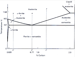
 Iron-Carbon Phase Diagram Its defined as:- A map of the
In their simplest form steels are alloys of Iron (Fe) and Carbon (C). Notes: -. This graph
 Phase Diagrams
3) The iron-carbon system phase transformations. 4) Transformation rate effects and TTT diagrams
 Iron Carbon/Cementite Phase Diagram
European Headquarters. BUEHLER Germany info.eu@buehler.com. BUEHLER France info.eu@buehler.com. BUEHLER United Kingdom info.eu@buehler.com. BUEHLER China.
 Iron Carbon Phase diagram Questions: 1. FCC is a more close
Lecture 23-24 : Iron Carbon Phase diagram. Questions: 1. FCC is a more close packed structure yet solubility of carbon in austenite which is FCC is higher.
 IRON –CARBON PHASE DIAGRAM
IRON –CARBON PHASE DIAGRAM. Page 2. Definition of structures: Various phases that appear on the Iron-. Carbon equilibrium phase diagram are as under
 1-10 Iron-Carbon (Fe-C) Phase Diagram
One of these occurs for theIron-Carbon (Fe-C) system. The five most important three-phase reactions that occur in phases diagrams are: 1- Eutectic – a liquid
 Phase Behavior in Iron/Carbon System
Martensite (non equilibrium BCT phase from quench of γ). BCC. Orthorhombic. Iron/Carbon Phase Diagram. Iron shows a eutectic with Carbon allowing for a lower
 Iron-Carbon Phase Diagram (a review) see Callister Chapter 9
In their simplest form steels are alloys of Iron (Fe) and. Carbon (C). The Fe-C phase diagram is a fairly complex one
 Heat treatment and properties of iron and steel
are dealing with plain carbon steels and cast irons. 3.1. Iron-Carbon Phase Diagram. The complete iron-carbon phase (or constitu- tional) diagram represents
 The Iron Carbon Phase Diagram
There is more to the iron-carbon phase diagram than related in the backbone. In particular there is some nomenclature that I avoided in the main text but
 IRON –CARBON PHASE DIAGRAM
Various phases that appear on the Iron-. Carbon equilibrium phase diagram are as under: • Austenite. • Ferrite. • Pearlite. • Cementite. • Martensite.
 Iron Steel and Swords script
The Iron Carbon Phase Diagram. There is more to the iron-carbon phase diagram than related in the backbone. In particular there is some.
 Iron-Carbon Phase Diagram (a review) see Callister Chapter 9
In their simplest form steels are alloys of Iron (Fe) and. Carbon (C). The Fe-C phase diagram is a fairly complex one
 Iron Carbon Phase diagram Questions: 1. FCC is a more close
Lecture 23-24 : Iron Carbon Phase diagram. Questions: 1. FCC is a more close packed structure yet solubility of carbon in austenite which is FCC is higher.
 Teach Yourself Phase Diagrams and Phase Transformations
11-Mar-2009 Parts 2-4 show you how to read and interpret simple phase diagrams describe the important iron-carbon phase diagram
 The Iron - Iron Carbide (Fe-Fe C) Phase Diagram
pearlite layered structure of two phases: ?-ferrite and cementite. (Fe Different percentage carbon implies different percentage of.
 Phase Behavior in Iron/Carbon System
Martensite (non equilibrium BCT phase from quench of ?). BCC. Orthorhombic. Iron/Carbon Phase Diagram. Iron shows a eutectic with Carbon.
 Iron-Carbon Phase Diagram Its defined as:- A map of the
In their simplest form steels are alloys of Iron (Fe) and Carbon (C). Notes: -. This graph
 Iron Carbon/Cementite Phase Diagram
European Headquarters. BUEHLER Germany info.eu@buehler.com. BUEHLER France info.eu@buehler.com. BUEHLER United Kingdom info.eu@buehler.com. BUEHLER China.
 Heat treatment and properties of iron and steel
Iron-carbon phase diagram. 2. 3.2. Correlation of mechanical properties with microstructures of slowly cooled carbon steels. 4. 4. Decomposition of ausenite.
 [PDF] IRON –CARBON PHASE DIAGRAM
Various phases that appear on the Iron- Carbon equilibrium phase diagram are as under: • Austenite • Ferrite • Pearlite • Cementite • Martensite
 [PDF] Iron-Carbon Phase Diagram Its defined as
Iron-Carbon Phase Diagram Its defined as:- A map of the temperature at which different phase changes occur on very slow heating and cooling in relation to
 [PDF] 1-10 Iron-Carbon (Fe-C) Phase Diagram
The five most important three-phase reactions that occur in phases diagrams are: 1- Eutectic – a liquid transforms into two solids upon cooling 2- Eutectoid –
 [PDF] The Iron Carbon Phase Diagram
There is more to the iron-carbon phase diagram than related in the backbone So let's start with a phase diagram that contains maximal information:
 [PDF] Iron-Carbon Phase Diagram (a review) see Callister Chapter 9
C Phase Diagram ? ?-ferrite - solid solution of C in BCC Fe • Stable form of iron at room temperature • The maximum solubility of C is 0 022 wt
 Iron-Carbon Diagram Explanation [PDF] - Mechanical E-Notes
Iron-Carbon Phase Diagram with Detailed Explanation: If the percentage of the carbon is in the range of 0 to 2 11 then it is called Steel and if the
 [PDF] Fe-C Diagram
IRON-CARBON (Fe-C) PHASE DIAGRAM (EXAMPLE 1) 2 important points - Eutectoid (B) ? ? ? +Fe 3 C - Eutectic (A) L ? ? +Fe 3 C Fe 3 C (cementite)
 [PDF] Iron-Iron carbide (Fe-Fe3C) Phase Equilibrium Diagram
The diagram shows the phases present at various temperatures for very slowly cooled Fe-C alloys with carbon content up to 6 67 Information given by the
The Iron Carbon Phase Diagram
There is more to the iron-carbon phase diagram than related in the backbone. In particular, there is some
nomenclature that I avoided in the main text but that is important for understanding other writings about iron and steel.
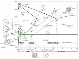
So let's start with a phase diagram that contains maximal information:Iron-carbon Phase Diagram
Source: Arabic Internet site
The important boundaries (the lines) separating phases have some universally used abbreviations:A1: The upper limit of the ferrite / cementite phase field (horizontal line going through the eutectoid point).
A2: The temperature where iron looses its magnetism (so-called Curie temperature). Note that for pure
iron this is still in the ˙-phase. A3: The boundary between the ˛ austenite and the austenite/ ferrite field. A4: The point in this case where ˙ changes to ˜ at high temperatures. ACM: The boundary between the ˛ austenite and the austenite / cementite field.Why would anybody abbreviate a temperature with the letter "A"? Well, it stands for "arrest", something that
happens in the slope of dilatometric or thermal curves recorded whenever phase diagrams where first measured.
Statements like "the addition of x lowers A3" are now clear.The circular insets give a schematic idea of what the structure would like at the compositions and temperatures
indicated.The next thing to know is that the phase diagrams above is actually not the true iron-carbon phase diagram. I lied to
you. Some mixture of cementite and iron is not the configuration that allows the system to achieve total nirvana. That
would be a iron - graphite mixture.All the cementite forming is just a transient phase on the way to nirvana; it will decay into pure carbon (graphite)
and iron in due time. Due time, however, means millennia and more at room temperature for plain carbon steel.
Cementite, in other words, is a very long-lived metastable phase under normal conditions. It thus makes sense to
use it for something that is not a true phase diagram for purists, but that sane normal folks will call "phase
diagram" anyway.We are also justified in doing this because the "real" iron - graphite phase diagram looks almost exactly like the
iron - cementite "phase diagram". Here is the proof:Iron, Steel and Swords script - Page 1Science
Iron - carbon phase diagram in comparison to
the iron cementite phase diagramDoes that mean that we don't have to worry about graphite being formed? Yes and no. Like almost always, it
depends:For plain carbon steel with carbon concentrations below 2 %, you needn't worry, indeed. Graphite is never formed
and the usual phase diagram covers everything nicely.For cast-iron, with carbon concentrations up to a few percent you need to worry. Graphite might form, depending
on conditions.For alloy steel, the usual thing nowadays, you need to worry, too. Some alloying elements, in particular silicon
(Si) but also nickel (Ni), promote graphite formation.Iron, Steel and Swords script - Page 2
quotesdbs_dbs7.pdfusesText_5[PDF] ironport email security configuration guide
[PDF] irr sharp el 738f
[PDF] irregular verbs in german pdf
[PDF] irregular verbs pdf with gujarati meaning
[PDF] irregular verbs pdf worksheet
[PDF] irregular verbs with malayalam meaning pdf
[PDF] irregular verbs with pictures pdf
[PDF] irs 1040 form 2018 pdf
[PDF] irs 1040 form 2018 printable
[PDF] irs 1040 form 2019 pdf
[PDF] irs 1099 form 2019
[PDF] irs 1099 hc
[PDF] irs 2019 tax deadline extended
[PDF] irs 2019 tax deadline extension
