[PDF] capteur ultrason ev3
[PDF] techniques calcul mental ce1
[PDF] objectif du calcul mental
[PDF] techniques calcul mental cycle 3
[PDF] apprendre caricature gratuitement
[PDF] dessin portrait pdf
[PDF] cours de dessin pdf gratuit
[PDF] technique de dessin au crayon visage
[PDF] apprendre ? dessiner le corps humain pdf
[PDF] le guide complet de l'artiste pour dessiner les vi
[PDF] conjugaison arabe futur
[PDF] conjugaison arabe accompli pdf
[PDF] les verbes français en arabe pdf
[PDF] livre pour apprendre le coréen pdf
[PDF] exercice coréen débutant

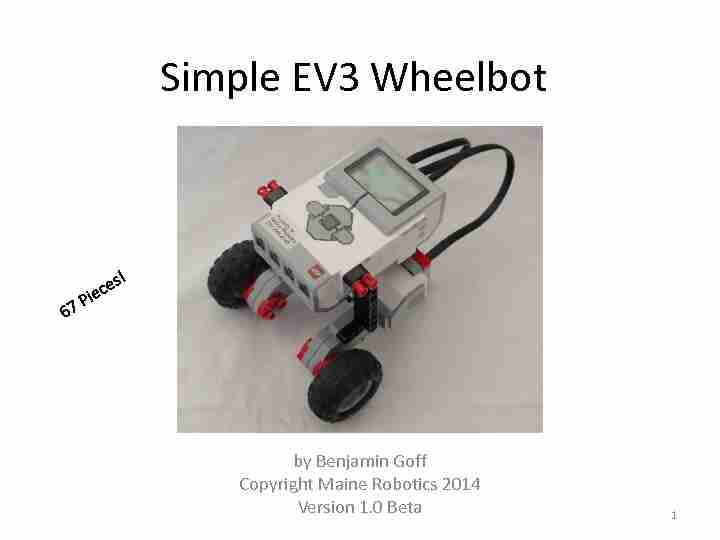
Simple EV3 Wheelbot
by Benjamin Goff
Copyright Maine Robotics 2014
Version 1.0
Beta 1
Parts List Pt 1
Wheels
Electronics
OR (1) EV3 Robot
Controller
(2) Large EV3 Motors (2) Mindstorm Wires, any size (2) Large Wheels
Note: the exact type of wheel
does not matter, but the two wheels must be identical!
The instructions will be using
the bottom left wheels, but feel free to experiment with different wheels (2) Small Pulley Wheels
2 Parts Pictures from Bricklink.com
Parts List Pt 2
Axle Connectors Beams / Technic Lift Arms
(5) 5-Hole Technic Lift Arms (2) 7-Hole Technic Lift Arms (2) 11 -Hole Technic Lift Arms (2) 3x5-Hole L Shaped
Bent Technic Lift Arms
(2) 2x4 -Hole L Shaped
Bent Technic Lift Arms
(1) Hole -Hole-Axle Connector,
Perpendicular (1) Axle-Hole-Axle Connector,
Perpendicular
3 Parts Pictures from Bricklink.com
Parts List Pt 3
Pins and Connectors Axles
(1) #3 Axle (3) #7 Axles
Note: Axles are measured by the number of
studs long they are. So a #7 Axle is 7 studs long if it is held next to a regular Lego brick. (4) Long Pins w/ Bushings (any color) (2) Axle Pins (1) Half Bushing (5+) Bushings (18+) Black Friction Pins (7) Black or Blue Long Pins
4 Parts Pictures from Bricklink.com
5
Parts Laid Out
Build Base Pt1
1.Build Bottom: Connect the
(5) 5-hole Technic Lift Arms using the Long Pins.
2.Build Back Horizontal
Reinforcers: Connect Friction
Pins to (2) 11-hole Technic Lift
Arms as shown in the lower
right hand figure. Lay out pieces as shown and push together, lining up holes on the Lift Arms 6
1. Bottom
2. Back Horizontal Reinforcers
Build Base Pt2
3.Attach Bottom pieces and
Back Horizontal Reinforcers
to Motors.
4.Note: the Motors have been
placed upside down in the picture! The bottoms of the Motors are a light gray, if you see white on top then flip the Motors over. 7
Build Pivot Wheel
1.Layout Pieces:
#7 Axle #3 Axle Axle-Hole-Axle Connector Hole-Hole-Axle Connector Half-
Bushing
(3) Full Bushings (2) Axle-Pins (2) Pulley Wheels
2.Slide Full Bushings, Half-Bushing, Hole-Hole-Axle
Connector, and Axle-Hole-Axle Connector onto #7
Axle. See upper right picture
3.Attach Pulley Wheels and #3 Axle to Hole-Hole-
Axle Connector (to the end hole) and push Axle-
Pins into Axle-Hole-Axle Connector.
Step 2 Order: Hole-Hole-Axle Connector,
Bushing, Bushing, Half-Bushing, Axle-Hole-
Axle Connector, Bushing
Axle-Pins
8
Attach Pivot Wheel to Base
Flip the Base over so that
the white tops of the
Motor are showing!
The Pivot Wheel should attach to the bottom
Back Horizontal
Reinforcer
9
Attach Large Wheels
(Drive Wheels)
1.Build Wheel and Axle Assemblies: Put
#7 Axle through Large Wheel and then slide on bushing. Repeat for the other wheel.
2.Put the Wheel and Axle Assemblies
through the center hole of the Motors.
Note: some wheels have a deeper
impression on one side than the other. The
Shallower side should face TOWARDS the
motors.
Upper wheel
shows deeper impression.quotesdbs_dbs2.pdfusesText_2


 TDDD63 Project: EV3 Lego Mindstorms Exercises - LiU