[PDF] Physique classification périodique
[PDF] Physique CNED Devoir 03
[PDF] Physique cned devoir 2
[PDF] Physique Cned seconde
[PDF] physique college free
[PDF] physique de l'atmosphère cours
[PDF] physique definition
[PDF] physique des ondes cours et exercices corrigés
[PDF] physique des ondes exercices corrigés
[PDF] physique des ondes pdf
[PDF] physique des réacteurs nucléaires pdf
[PDF] physique devoir 1 cned seconde la galere :((((((((
[PDF] physique devoir 1 cned seconde, aider moi svp ,je
[PDF] Physique devoir 1 seconde
[PDF] physique devoir 1 seconde cned aider moi svp

1 Copyright 2001, Regents of University of California
Handout on RC Circuits. A.R. Neureuther
Version Date 09/08/03EECS 42 Intro. Digital Electronic, Fall 2003
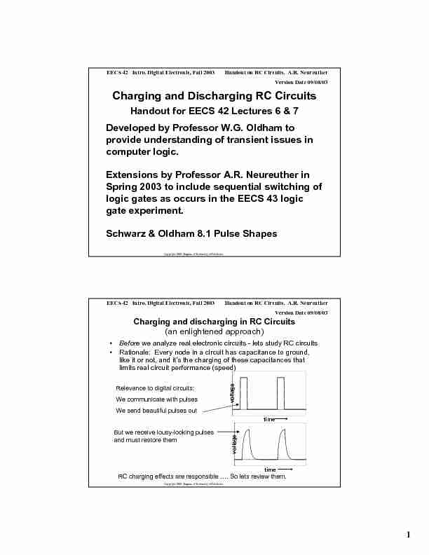
Charging and Discharging RC Circuits
Handout for EECS 42 Lectures 6 & 7
Developed by Professor W.G. Oldham to
provide understanding of transient issues in computer logic.
Extensions by Professor A.R. Neureuther in
Spring 2003 to include sequential switching of
logic gates as occurs in the EECS 43 logic gate experiment.
Schwarz & Oldham 8.1 Pulse Shapes
Copyright 2001, Regents of University of CaliforniaHandout on RC Circuits. A.R. Neureuther Version Date 09/08/03EECS 42 Intro. Digital Electronic, Fall 2003
Charging and discharging in RC Circuits
(an enlightened approach) •Beforewe analyze real electronic circuits - lets study RC circuits • Rationale: Every node in a circuit has capacitance to ground, like it or not, and it's the charging of these capacitances that limits real circuit performance (speed) RC charging effects are responsible .... So lets review them.Relevance to digital circuits:
We communicate with pulses
We send beautiful pulses outtime
voltage
But we receive lousy-looking pulses
and must restore themtime voltage 2 Copyright 2001, Regents of University of California
Handout on RC Circuits. A.R. Neureuther
Version Date 09/08/03EECS 42 Intro. Digital Electronic, Fall 2003
LOGIC GATE DELAY τ
D
Time delay τ
D occurs between input and output: "computation" is not instantaneous
Value of input at t = 0
determines value of output at later time t = τ D A BF 0 11
0Logic State
tt D 00
Input (A and B tied together)
Output (Ideal delayed step-function)
Actual exponential voltage versus time.
Capacitance to Ground
F Copyright 2001, Regents of University of California
Handout on RC Circuits. A.R. Neureuther
Version Date 09/08/03EECS 42 Intro. Digital Electronic, Fall 2003 t t tLogic state 2τ 0
τSIGNAL DELAY: TIMING DIAGRAMS
Show transitions of variables vs time
1 0 t
τ2τ3τ
Note that Cchanges two gate delays
after Aswitches.
Note Bchanges one gate delay
after Aswitches ABCD A B D C
Note that Dchanges threegate delays
after Aswitches.
Oscilloscope Probe
Timing Diagrams are an extension of the logic diagrams in O&S Ch 11 & 12 3 Copyright 2001, Regents of University of California
Handout on RC Circuits. A.R. Neureuther
Version Date 09/08/03EECS 42 Intro. Digital Electronic, Fall 2003
Simplification for time behavior of RC Circuits
Before any input change occurs we have a dc circuit problem (that is we can use dc circuit analysis to relate the output to the input).
We call the time period
during which the output changes the transient
We can predict a lot about the
transient behavior from the pre- and post-transient dc solutions time voltage input time voltage outputLong after the input change occurs things "settle down" ....
Nothing is changing .... So
quotesdbs_dbs2.pdfusesText_2
 1 Copyright 2001, Regents of University of California
  1 Copyright 2001, Regents of University of California
  RC Circuits - New York University