[PDF] regle routage carte electronique
[PDF] regle de routage pcb
[PDF] realisation d'un circuit imprimé de a ? z
[PDF] les étapes de fabrication d'une carte électronique
[PDF] formule manning strickler excel
[PDF] ecriture journalistique formation
[PDF] dsciences libreoffice
[PDF] écrire une note d'intention artistique
[PDF] l'opinion maroc contact
[PDF] extension dsciences
[PDF] abonnement ? l éveil
[PDF] dsciences télécharger
[PDF] l'opinion telephone
[PDF] journal l'opinion adresse
[PDF] l opinion numéro de téléphone

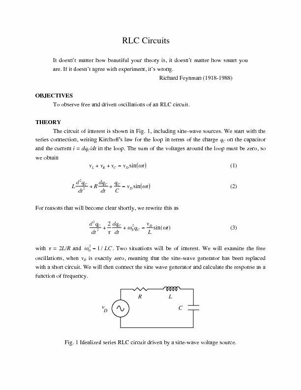
 Chapter 21: RLC Circuits - Department of Physics