The Software Developer Kit (SDK) provides compiled binaries in Java (v1.6) and . o Business Rule X0000-010 - For each SubmissionID provided in the ...
p
<%@ taglib uri="http://java.sun.com/jsp/jstl/core" prefix="c" %>. <%@ page import = "java.util.*" %>. <html>. <head> <title> DateTime </title> </head>.
Bsc(P) VI InternetTechnologies
run it you must install the latest version of Oracle Java (1.8 or above). upgrade any older version of Java by installing the patch upgrades available.
edir install
Azar 13 1388 AP The Java API for XML Processing (JAXP) enables applications to parse
xml error troubleshooting guide
A Formalization of Java's Concurrent Access Modes
In this paper we present the first formalization of Java's access modes. X000. Sometimes. Sometimes. X001. Sometimes. Sometimes. X002. Sometimes.
(x000 USD). Location. (Province Regency/City) Central Java Province18. 2020. 5
Climate Resilience Funding
Quantitative seismic reservoir characterisation: A model-based
approach for the Sampang PSC East Java
Device. Bit Address. Word Address. 16 bit 32 bit. Input Relay. X0000-XFFFF. X0000-XFFF0*1. Output Relay. Y0000-YFFFF. Y0000-YFFF0*1. Internal Relay.
MitsubishiMelsecQUDPea
Oracle and Java are registered trademarks of Oracle and/or its affiliates. Other names may be trademarks of their respective owners.
E
Farvardin 27 1400 AP rainfall during the dry season in June-August
IndonesiaBUR FINAL REPORT
210118

1System Structure
2
Supported Device Addresses
3
Consecutive Device Addresses
4
Environment Setup
5
I/O Manager Configuration
6
Driver Configuration
7
Protocol Configuration
8
Device Address Configuration
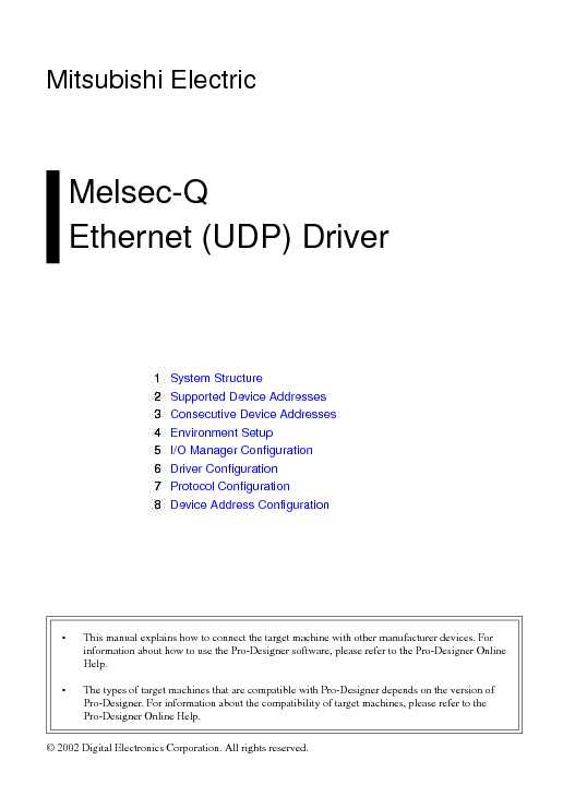
Mitsubishi Electric
Melsec-Q
Ethernet (UDP) Driver
• This manual explains how to connect the target machine with other manufacturer devices. For information about how to use the Pro-Designer software, please refer to the Pro-Designer Online Help. • The types of target machines that are compatible with Pro-Designer depends on the versio n of Pro-Designer. For information about the compatibility of target machines, please refer to the
Pro-Designer Online Help.
© 2002 Digital Electronics Corporation. All rights reserved. 2 Mitsubishi Electric Melsec-Q Ethernet (UDP) Driver
1 System Structure
The following table describes the basic system setup for connecting targets machine to Mitsubishi
Melsec-Q Series PLCs.
Series CPU Ethernet Module
MELSEC-Q Series
Q00CPU
Q00JCPU
Q01CPU
Q02CPU
Q02HCPU
Q06HCPU
Q12HCPU
Q25HCPUQJ71E71QJ71E71-B2
Use a 10BASE-T connection for PS Series Type G, PS Series Type P, and GP2000 Series target machines. 3 Mitsubishi Electric Melsec-Q Ethernet (UDP) Driver
2 Supported Device Addresses
The following table lists the device address ranges you can enter from t he Device Address keypad. For actual device address ranges supported by the PLC, refer to the co rresponding PLC manual Supported device addresses differ from protocol to protocol and between PLC models.
Device Bit Address Word Address 16 bit 32 bit
Input Relay X0000-XFFFF X0000-XFFF0
*1
Output Relay Y0000-YFFFF Y0000-YFFF0
*1
Internal Relay M00000-M65535 M00000-M65520
*2
Latch Relay L00000-L65535 L00000-L65520
*2
Special Relay SM0000-SM9999 SM0000-SM9984
*2
Annunciator F00000-F65535 F00000-F65520
*2
Edge Relay V00000-V65535 V00000-V65520
*2
Step Relay S0000-S9999 S0000-S9984
*2
Link Relay B0000-BFFFF B0000-BFFF0
*1
Special Link Relay SB000-SBFFF SB000-SBFF0
*1
Timer (contact) TS00000-TS65535 --
Timer (coil) TC00000-TC65535 --
Retentive Timer (contact) SS00000-SS65535 --
Retentive Timer (coil) SC00000-SC65535 --
Counter (contact) CS00000-CS65535 --
Counter (coil) CC00000-CC65535 --
Timer (current value) -- TN00000-TN65535
Retentive Timer (current value) -- SN00000-SN65535
Counter (current value) -- CN00000-CN65535
Data Register
*3
D00000:0-D65535:15 D00000-D65535
*4
Special Register
*3
SD0000:0-SD9999:15 SD0000-SD9999
*4
Link Register
*3
W0000:0-WFFFF:F W0000-WFFFF
*5
Special Link Register
*3
SW000:0-SWFFF:F SW000-SWFFF
*5
File Register(Normal)
*3
R00000:0-R65535:15 R00000-R65535
*4
0R0000:0-0R7FFF:F 0R0000-0R7FFF
*5
1R0000:0-1R7FFF:F 1R0000-1R7FFF
*5
2R0000:0-2R7FFF:F 2R0000-2R7FFF
*5
30R0000:0-30R7FFF:F 30R0000-30R7FFF
*5
31R0000:0-31R7FFF:F 31R0000-31R7FFF
*5 L/H
