DIODES INC. (1N4742A-T) ZENER DIODE DO-41 1W 12V ROHS
www.diodes.com ã Diodes Incorporated. 1N4728A - 1N4761A. 1.0W ZENER DIODE. Characteristic. Symbol. Value. Unit. Zener Current (see Table page 2).
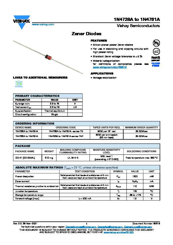
1N4728A to 1N4761A Zener Diodes
25 nov. 2021 Silicon planar power Zener diodes ... liability for any errors inaccuracies or incompleteness contained in any datasheet or in any other.
n a
BZX85-Series Zener Diodes
25 nov. 2021 Hyperlinks included in this datasheet may direct users to third-party websites. These links are provided as a convenience and for informational ...
bzx
BZX55-Series Small Signal Zener Diodes
Small Signal Zener Diodes disclaim any and all liability for any errors inaccuracies or incompleteness contained in any datasheet or in any other.
bzx
Zener Diode
Zener voltage 3.3V to 12V. •. Vz-tolerance ±5%. Applications: Voltage stabilization. Absolute Maximum Ratings. Tj = 25°C. Parameter. Test Conditions.
ZMY3V9 to ZMY75 Zener Diodes
25 nov. 2021 Silicon planar power Zener diodes ... liability for any errors inaccuracies or incompleteness contained in any datasheet or in any other.
zmy v
Various Mfrs (1N4733A) DIODEZENER
5.1V
ZPY3V9 to ZPY75 Zener Diodes
25 nov. 2021 Silicon planar power Zener diodes ... liability for any errors inaccuracies or incompleteness contained in any datasheet or in any other.
zpy v
DATA SHEET
4 juil. 2003 DATA SHEET. Page 1 of. The enclosed information is believed to be ... BZX12 12V 1.3W ZENER DIODE. 47-3076 n/a. BZX13 13V 1.3W ZENER DIODE.
e
MMSZ5221BT1 - Zener Voltage Regulators 500 mW SOD-123
Three complete series of Zener diodes are offered in the convenient surface mount plastic SOD−123 package. this data sheet. DEVICE MARKING INFORMATION.
mmsz bt d

1N4728A to 1N4761A
www.vishay.comVishay Semiconductors
Rev. 2.5. 25-Nov -20211Document Number: 85816
For technical questions within your region: DiodesAmericas@vishay.com , DiodesAsia@vishay.com, DiodesEurope@vishay.comTHIS DOCUMENT IS SUBJECT TO CHANGE WITHOUT NOTICE. THE PRODUCTS DESCRIBED HEREIN AND THIS DOCUMENTARE SUBJECT TO SPECIFIC DISCLAIMERS, SET FORTH AT www.vishay.com/doc?91000
Zener Diodes
LINKS TO ADDITIONAL RESOURCESFEATURES
Silicon planar power Zener diodes
For use in stabilizing and clipping circuits with high power rating Standard Zener voltage tolerance is ± 5 %
Material categorization:
for definitions of compliance please see www.vishay.com/doc?99912APPLICATIONS
Voltage stabilization
PRIMARY CHARACTERISTICS
PARAMETER VALUE UNIT
V Z range nom. 3.3 to 75 VTest current I
ZT3.3 to 76 mA
V Z specification Thermal equilibriumCircuit configuration Single
333DDD 3 D
3D Models
ORDERING INFORMATION
DEVICE NAMEORDERING CODETAPED UNITS PER REELMINIMUM ORDER QUANTITY1N4728A to 1N4761A 1N4728A to 1N4761A -series-TR 5000 per 13" reel 25 000/box
1N4728A to 1N4761A 1N4728A to 1N4761A-series-TAP
5000 per ammopack
(52 mm tape)25 000/boxPACKAGE
PACKAGE NAMEWEIGHT
MOLDING COMPOUND
FLAMMABILITY RATINGMOISTURE SENSITIVITY
LEVELSOLDERING CONDITIONS
DO-41 (DO-204AL) 310 mg UL 94 V-0
MSL level 1
(according J-STD-020)Peak temperature max. 260 °CABSOLUTE MAXIMUM RATINGS (T
amb = 25 °C, unless otherwise specified)PARAMETERTEST CONDITIONSYMBOLVALUEUNIT
Power dissipationValid provided that leads at a distance of 4 mm from case are kept at ambient temperatureP tot1300 mW
Zener currentI
Z P V /V Z mAThermal resistance junction to ambient air
Valid provided that leads at a distance of 4 mm
from case are kept at ambient temperatureR thJA110 K/W
Junction temperature
T j175 °CStorage temperature range
T stg-65 to +175 °CForward voltage (max.) I
F = 200 mA V F 1.2 V1N4728A to 1N4761A
www.vishay.comVishay Semiconductors
Rev. 2.5. 25-Nov -20212Document Number: 85816
For technical questions within your region: DiodesAmericas@vishay.com , DiodesAsia@vishay.com, DiodesEurope@vishay.comTHIS DOCUMENT IS SUBJECT TO CHANGE WITHOUT NOTICE. THE PRODUCTS DESCRIBED HEREIN AND THIS DOCUMENTARE SUBJECT TO SPECIFIC DISCLAIMERS, SET FORTH AT www.vishay.com/doc?91000
Notes (1) Based on DC measurement at thermal equilibrium while maintaining the lead temperature (T L1N4728A to 1N4761A
www.vishay.comVishay Semiconductors
Rev. 2.5. 25-Nov -20211Document Number: 85816
For technical questions within your region: DiodesAmericas@vishay.com , DiodesAsia@vishay.com, DiodesEurope@vishay.comTHIS DOCUMENT IS SUBJECT TO CHANGE WITHOUT NOTICE. THE PRODUCTS DESCRIBED HEREIN AND THIS DOCUMENTARE SUBJECT TO SPECIFIC DISCLAIMERS, SET FORTH AT www.vishay.com/doc?91000
Zener Diodes
LINKS TO ADDITIONAL RESOURCESFEATURES
Silicon planar power Zener diodes
For use in stabilizing and clipping circuits with high power rating Standard Zener voltage tolerance is ± 5 %
Material categorization:
for definitions of compliance please see www.vishay.com/doc?99912APPLICATIONS
Voltage stabilization
PRIMARY CHARACTERISTICS
PARAMETER VALUE UNIT
V Z range nom. 3.3 to 75 VTest current I
ZT3.3 to 76 mA
V Z specification Thermal equilibriumCircuit configuration Single
333DDD 3 D
3D Models
ORDERING INFORMATION
DEVICE NAMEORDERING CODETAPED UNITS PER REELMINIMUM ORDER QUANTITY1N4728A to 1N4761A 1N4728A to 1N4761A -series-TR 5000 per 13" reel 25 000/box
1N4728A to 1N4761A 1N4728A to 1N4761A-series-TAP
5000 per ammopack
(52 mm tape)25 000/boxPACKAGE
PACKAGE NAMEWEIGHT
MOLDING COMPOUND
FLAMMABILITY RATINGMOISTURE SENSITIVITY
LEVELSOLDERING CONDITIONS
DO-41 (DO-204AL) 310 mg UL 94 V-0
MSL level 1
(according J-STD-020)Peak temperature max. 260 °CABSOLUTE MAXIMUM RATINGS (T
amb = 25 °C, unless otherwise specified)PARAMETERTEST CONDITIONSYMBOLVALUEUNIT
Power dissipationValid provided that leads at a distance of 4 mm from case are kept at ambient temperatureP tot1300 mW
Zener currentI
Z P V /V Z mAThermal resistance junction to ambient air
Valid provided that leads at a distance of 4 mm
from case are kept at ambient temperatureR thJA110 K/W
Junction temperature
T j175 °CStorage temperature range
T stg-65 to +175 °CForward voltage (max.) I
F = 200 mA V F 1.2 V1N4728A to 1N4761A
www.vishay.comVishay Semiconductors
Rev. 2.5. 25-Nov -20212Document Number: 85816
For technical questions within your region: DiodesAmericas@vishay.com , DiodesAsia@vishay.com, DiodesEurope@vishay.comTHIS DOCUMENT IS SUBJECT TO CHANGE WITHOUT NOTICE. THE PRODUCTS DESCRIBED HEREIN AND THIS DOCUMENTARE SUBJECT TO SPECIFIC DISCLAIMERS, SET FORTH AT www.vishay.com/doc?91000
Notes (1) Based on DC measurement at thermal equilibrium while maintaining the lead temperature (T L