 Piper J3 und PA18 Bauanleitung
Die. Page 14. Copyright © 2000 Toni Clark practical scale GmbH Zeiss-Str.10 D-32312 Lübbecke Tel.05741/5035 Fax.05741/40338. PIPER J3 UND PA18 BAUANLEITUNG. 14.
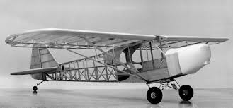
 Piper PA-18-95 Super Cub
The Piper PA-18 Super Cub could be fitted with either a Continental four Reklamationen können nur bearbeitet werden wenn die Bauanleitung
 Toni Clark Katalog 2013
so löblichen Baukasten und Bauplan der Piper J3 von practical scale hocke Piper J3 Cub und PA18. Aus dem Vollen gedreht. Abmessung: 49 x 29 mm. Gewicht ...
 Untitled
Eine Explosionszeichnung des Modelles ist in der Mitte dieser Bauanleitung Die PIPER PA 18 SUPER CUB ist ein zweisitziger abgestrebter Hochdecker. Ein.
 Building Instructions Piper J3 and PA18
Piper J3 and PA18 Building Instructions. 1. Piper J3 Cub und PA18. Building Instructions. Page 2. Toni Clark practical scale GmbH Zeiss-Str.10 D-32312 Luebbecke
 Ripmax - PIPER J-3 Cub
Änderungen des Aufbaus und Nichteinhalten der Betriebsanleitung führen zum. Verlust jeglicher Gewährleistungs-oder Haftungsansprüche. Da Hersteller und
 Der folgende Bericht ist in Ausgabe 06/2020 des Magazins
War die alte Cub eher einer. Piper Pa-18 nachempfunden so könnte das Vorbild der Neuen die Carbon Die Stückliste ist in der Bauanleitung aufgeführt.
 LISTE DER ERGÄNZUNGEN ZUR MUSTERZULASSUNG
10.11.2000 Piper J3 PA-11
 ORATEX® Verarbeitungsanleitung & Ergänzung zum
02.10.2015 Piper. PA-18. LBA 722. 18/08/2014. Piper. PA-20. LBA 727. LBA EMZ SA 1468 Issue 2. Piper. PA-22. LBA 712. Piper. J3 / PA11. LBA 713. Robin.
 Piper J-3 Cup
BEDIENUNGSANLEITUNG / INSTRUCTION MANUAL PIPER J-3 CUP. 8. INHALTSABBILDUNG. INHALT. NR. TEIL. MENGE. 1. Piper J-3 Cup. 1. 2. Fernsteuerung. 1. 3. Anleitung. 1.
 Building Instructions Piper J3 and PA18
Our Piper J3 Cub kit has been in continuous production since 1976. This kit being the first anywhere in the world designed expressly for (at that time)
 1700mm PA-18 Super Cub
The Piper PA-18 Super Cub is a two-seat single-engine monoplane. Bauanleitung) und kontaktieren Sie Ihren lokalen Händler oder.
 Toni Clark Katalog 2013
20 Piper J3 und Piper PA 18. 24 CAP 21 Bauplan die Bauanleitung mit Stückliste und die Scale- ... lung zur „PA 18 Super Cub“ mit Motoren bis 150 PS.
 VQ Super Cub 30cc instruction_x_pdf.cdr
PIPER PA-18. Radio control model. R/C Flugmodell. MONTAGEANLEITUNG. INSTRUCTION MANUAL. SPECIFICATIONS. Wingspan. 106.6in. Length. 67.7 in. Electric Motor.
 Ripmax - PIPER J-3 Cub
Modell-. Multicopter Modell-Hubschrauber
 piper pa -18 super cub
Torque servos: 11.3kg/cm – 12.9kg/cm. PIPER PA -18 SUPER CUB. Item code: BH172. Instruction manual. Servo extension leads.
 PIPER Cub
Lesen Sie vor dem Bau Ihres Modells unbedingt die Sicherheits- hinweise genau durch. Halten Sie sich stets an die in den Anlei-.
 Der Profi für den Scale-Großmodell-Bau
Cessna 150/152 lieferbar in ver- schiedenen Größen und Bausatz- ausstattungen. Beispielsweise von. Hostetler mit 3.048 mm Spann- weite. Piper J3 oder PA 18
 Räder Bremsen Hauptfahrwerk
PA-18 (Piper). Räder / Bremsen. PA-18 original Fahrwerk. 1.25" / 1.50". STC-020.2 2x Hauptfersenbremszylinder /Hebel/Bremsflüssigkeitbehälter AV-CUB-124.
 Der folgende Bericht ist in Ausgabe 06/2020 des Magazins
Hier finden sich alle Teile und eine sehr gute Bauanleitung. Was aller- Piper Pa-18 nachempfunden so könnte das Vorbild der Neuen die Carbon. Cub von ...
PIPER PA-18
Radio control model
R/C Flugmodell
MONTAGEANLEITUNG
INSTRUCTION MANUAL
SPECIFICATIONS
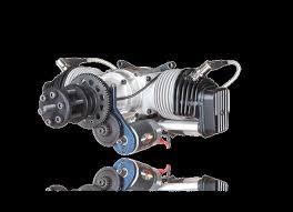
Wingspan 106.6in. Length 67.7 in. Electric Motor (See next page)Glow Engine 26-30cc two stroke
Radio 6 Channel / 8 ServosWARNING! This radio controlled model is NOT a toy. If modified or flown carelessly it could go out of controll and
cause serious human injury or property damage. Before flying your airplane, ensure the air field is spacious enough.
Always fly it outdoors in safe areas and seek professional advice if you are unexperienced.ACHTUNG!
Dieses ferngesteuerte Modell ist KEIN Spielzeug! Es ist für fortgeschrittene Modellflugpiloten bestimmt,
erwendung kannTECHNISCHE DATEN
Spannweite 2710mm Lange 1720mmVerbrennerantrieb 26-30cc 2-T
Fernsteuerung 6 Kanal / 8 Servos
ARF BY
SUPER CUB
1.5mm AB !CAL/RAssemble left and right
sides the same wayXDrill holes using the stated
size of drill (in this case 1.5 mm Ø)Use epoxy glue
Take particular care here
Hatched-in areas:remove covering
film carefullyNot included.
These parts must be
purchased separatelyCheck during assembly that these
parts move freely, without bindingApply cyano glueLow setting
SILICON
EPOXY A
EPOXY BCA
GLUEEpoxy Glue (5 minute type)
Silicon sealer
Cyanoacrylate
GlueMinimum 6 channel radio
for airplane with 8 servosNylon tubeExtension for aileron servo, Flap servo.REQUIRED FOR OPERATION (Purchase separately)
Epoxy Glue (30 minute type)
TOLLS REQUIRED
Hobby knife
Needle nose Pliers
Phillip screw driver
AwlScissorsWire Cutters(Purchase separately)
Hex W rench Masking tape - Straight Edged Ruler - Pen or pencil - Drill andAssorted Drill BitsRead through the manual before you begin, so you will have an overall idea of what to do.(Purchase separately).Motor control x1 .Aileron x2
.Elevator x2 .Rudder x1 .Flap x 2CONVERSION TABLE1.0mm = 3/64"
1.5mm = 1/16"
2.0mm = 5/64"
2.5mm = 3/32"3.0mm = 1/8"
4.0mm = 5/32"
5.0mm = 13/64"
6.0mm = 15/64"10mm = 13/32"
12mm = 15/32"
15mm = 19/32"
20mm = 51/64"25mm = 1"
30mm = 1-3/16"
45mm = 1-51/64"If exposed to direct sunlight and/or heat, wrinkels can appear
. Storing the model in a cool place will let the wrinkles disappear . Otherwise, remove wrinkles in covering film with a hair dryer , starting with low temperature.You can fix the corners by using a hot iron.
fen bzw. Falten entstehen. VABFLUG (Nicht enthalten)
Klebstoff
Epoxy-Klebstoff (30min-Typ)
Epoxy-Klebstoff (5min-Typ)Gas Engine: 26 ~ 30cc
35mm19mmHORIZONT
AL STABILIZERCut two slots (only the covering) on the top and along the trailing edge of the horizontal stabilizer.TOP VIEW / DraufsichtT
OP VIEW / Draufsicht19mm35mm1Full the elevator out of the horizontal stabilizer .2Cut away only the covering both sideCut away only the covering on the top and bottom3 4 The slot on the horizontal stabilizer and the slot on the fuselage must be coincidental.AA 'A=A Trial fit the horizontal stabilizer in place . Check the alignment of the horizontal stabilizer . When you are satisfied with the alignment, use a pencil to trace around the top and bottom of the stabilizer where it meets the fuselage.5HORIZONTAL STABILIZER - VERTICAL STABILIZER
Cut away only the covering
on the top and bottom6 Remove the horizontal stabilizer from the fuselage. Using the sharp hobby knife, carefully cut away the covering inside the lines which were marked above.7CAThin CA glue CA CACAThe elevator hinges are pre-glue into the
elevator halves. W orking with one elevator half for now , apply a thin layer of petroleum jelly to only the pivot point of the two hinges.Without using glue yet, push the elevator half and its hinges into the hinge slots in the trailing edge of the horizontal stabilizer. There should be a minimal hinge gap and the end of the elevator half should not rub against the horizontal stabilizer.When satisfied with the fit and alignment, hinge
the elevator half to the horizontal stabilizer, using thick CA glue. Make sure to apply a thin layer of CA glue to the top and bottom of both hinges. Repeat the previous procedures to hinge the second elevator half to the other side of the horizontal stabilizer. Pull the horizontal stabilizer through the other side of the fuselage and repeat the previous procedures to glue the second torque rod wire into the horizontal stabilizer.Realign the horizontal stabilizer
, then glue the horizontal stabilizer into the fuselage, using a generous amount of thin CA. Apply thin CA to each of the four joints and use a generous amount to ensure to strong bond.8 NOTE:You may need to open up the slots of the
horizontal stabilizer so that the vertical stabilizer is not too difficult to push in.Cut away only the covering both sides.9 10 Trial fit the vertical stabilizer in place . Check the alignment of the vertical stabilizer . When you are satisfied with the alignment, use a pencil to trace around the right and left of the stabilizer where it meets the fuselage.Cut away only the covering on the left and right side. Remove the vertical stabilizer from the fuselage. Using the sharp hobby knife, carefully cut away the covering inside the lines which were marked above.AB Realign the vertical stabilizer , ensure that the vertical stabilizer is perpendicular to the horizontal stabilizer Then glue the vertical stabilizer into the fuselage, using a generous amount of 5 min. Epoxy. Apply thin epoxy to each of the two joints and the entire bottom edge of the vertical stabilizer, use a generous amount to ensure to strong bond.5 min.Epoxy1
11213
2mm3x12mm screw
CAApply a thin layer of petroleum
jelly to only the pivot point of the torque rod bearing. Glue the rudder torque rod bearing into the slot you cut previously in the vertical stabilizer, using a thin layer of CA glue.Petroleum jellyFUSELAGE - SIDE VIEWVERTICALSTABILIZER3x12.......2
....................2TAIL WHEEL
.....64X20mm screwCut away only the covering
* WARNING: When removing any covering
from the airframe, please ensure that you secure the cut edge with CA or similar cement.This will ensure the covering remain tight.3mm
BOTT OM - VIEW / Unteransicht......4Connector3mm connector3mm connector
Aluminum landing
gearHauptfahrwerk3mm connectorBOTTOM - VIEW / UnteransichtBOTT
OM - VIEW / UnteransichtMAIN LANDING GEAR
MAIN LANDING GEAR
MAIN LANDING GEAR
...1Aluminum landing gearHauptfahrwerk4x30mm screw4mm nut............24X40mm screw4mm nut-washer
BOTTOM - VIEW / UnteransichtAluminum landing
gearHauptfahrwerk4x30mm screw4mm nut3mm connector
FUSELAGEMAIN LANDING GEAR
MAIN LANDING GEAR
5mm13/64" Using a aluminum motor mounting plate as a template, mark the fire-wall
where the four holes are to be drilled (1). Remove the aluminum motor mounting plate and drill a 5mm hole
through the plywood at each of the four marks marked (2).Note: The aluminum motor mounting and screws included with the engine.134Aluminum motor
mounting plate 25BB=152-158mm
6 .........45X60mm screw5mm washer
5mm nut..................16
..................12ENGINE BB=152-158mm Using a aluminum motor mounting plate as a template, mark the fire-wall where the four holes are to be drilled (1). Remove the aluminum motor mounting plate and drill a 5mm hole through the plywood at each of the four marks marked (2).Note:The aluminum motor mounting and screws
included with the motor .2.mm2.mmRelive the cowl to clear the silencer
carburetor and plug. 23x8mm screw ............4ELECTRIC MOTORCOWLING
4 - 6mm
Akku Kiettband
aus demPICHLER
Sortiment
Best.Nr. C4739
Fuel tank seat bell
XTippFuel tank flat (3mm plywood)
30cc Fuel tank
Fuel tank seat bellLi-po batteryFuel tank assemblyFUELTANK & LIPO. BATTERY
Throttle
pushrodFRONTServo trayElevator
pushrodElevator servoRudder servoThrottle servoServo tray
FUELTANKRudder
pushrodSERVO TRAY - TOP VIEWFRONT REAR IN CASE OF
THE ELEVATOR SERVO IN SIDE
OFTHE FUSELAGEIN CASE OF
THE ELEVATOR SERVO
OUTSIDE OF THE FUSELAGESER
VOControl horn
......................42x30mm screw
...................8XAileron, flap servo and light extension cord not include.2x10mm screw2x10mm screwFlap servo hatchFlap servoServo mount Aileron servo hatchAileron servoServo mountWING BOTTOMWING BOTT
OMAileron (Flap) servo hatch
Aileron ( flap) push rodAileron (flap) control horn W ing - Bottom view / UnteransichtBOTT OM - VIEW / UnteransichtServo hatchPushrodAileron servo and hatchRIGHTAileron servo and hatch
LEFT1.5mm1.5mm
Flap servo and hatch
RIGHTFlap servo and hatch
LEFTWING SECTION2mm2X30mm...............4ConnectorSER VOL/RAssemble left and right
wing halves the same wayAluminum tube
BOTTOM - VIEW / Unteransicht
Cut away only
the covering CA CAL/RDo the same way with other
wing halves.Slide the aluminum tube into the fuselage as shown.WING WING3x12mm
.........4 .........4L/RDo the same way with
other wing halves.Secure the wing halves in place using 5x20mm screw .5x20mm5mm washer.......2
..................2Cut away only
the coveringCAFRONT
FRONTLEFT
BRACE (TOP VIEW)RIGHT
BRACE (TOP VIEW)
BOTTOM - VIEW / Unteransicht3x12mm
1.5mmL/RDo the same way with other
wing halves.3x12mm .........2WING
WING WING0.7mm dia. Cable
...1 roll2mm metal tube.....................4StabilizerCA
CA2mm metal tube
..............4BOTTOM - VIEW
Unteransicht..............2
3x6.......2T
AILT AILT AILIMPORTANT:Please do not clean your model with pure alcohol, only use liquid soap with water or use glass cleaner to clean on surface of
your model to keep the colour not fade.All details are subject to change
without notice !Technische Anderungen und Irrtumer vorbehalten ! CAX2x6mm
..........61mm BURDAVERSIONAUSTRIA
quotesdbs_dbs25.pdfusesText_31[PDF] BAUANLEITUNG „WEIHNACHTSKRIPPE“
[PDF] Bauanleitunge und Laubsäge-Vorlage für das Schwingtier
[PDF] Bauarbeiten: Frohe Zukunft ab 2. Mai Straßenbahn-frei
[PDF] BAUART - Architecture
[PDF] Bauart, la créativité au service de la durabilité
[PDF] Bauart, Type, Modèle ASK - Anciens Et Réunions
[PDF] Bauaufsichtlich anerkannte Prüf—, Überwachungs
[PDF] Baubericht KRUPP TITAN Dreiachs
[PDF] Bauberufe des Mittelalters
[PDF] Baubeschreibung - Karlin Immobilien
[PDF] Baubeschreibung - Wohnungen in Lüneburg
[PDF] Baubiologie Thiesen - Baubiologischer Arbeitskreis Westerwald
[PDF] Baubiologische Schimmelpilzentfernung nach - Special
[PDF] Baucenter Decker-Ries | Paperjam Guide
