 The exponential Fourier series for a periodic signal was developed in
Example 6.3 A half-rectified sine wave. Passing a sine wave of angular frequency N through a half-wave rectifier produces the signal shown in Figure 6.10
 Fourier Series
Fourier Series: Half-wave Rectifier. ( ). (. ) π π π ω π ω π ω π ω ω π ω π ω π ω π. E. E t. E tdt. E dttu a. = -. -. = -. = = = ∫. ∫-. 0cos cos. 2 cos. 2 sin.
 CHAPTER 4 FOURIER SERIES AND INTEGRALS
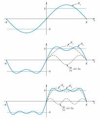
Example 1 Find the Fourier sine coefficients bk of the square wave SW(x). multiple of cosx is closest to f = cos3 x? 7. Sketch the 2π-periodic half wave ...
 Essential Mathematical Methods for Physicists - Weber and Arfken.1.1
This is our Fourier exponential series [Eq. (14.32)]. Separating real and This is the output of a simple half-wave rectifier. It is also an ap ...
 Table 15
Half wave rectified sine wave: 0. 2. T π ω After some algebra the delay can be represented as a phase shift in the Fourier series of the voltage waveform.
 Fourier_Series_continuous_time_periodic_signal_and_ Fourier
c = Fourier coefficients of exponential form of Fourier series. When a waveform has half wave symmetry the Fourier series will consist of odd harmonic terms.
 Unit 4 (Fourier Series & PDE with Constant Coefficient)
04-May-2020 n=1 n-1. So Half range sine series of f(x) on (0
 Untitled
26-Apr-2007 Continuous-Time Complex-Exponential Fourier Series Complex exponential Fourier ... half-wave rectifier. Page 4. (b) Suppose the input sinusoid x ...
 CHAPTER 3. SPECTRUM REPRESENTATION 58 - 3-4 Fourier Series
08-Sept-2012 ... exponential signal—the integral of a complex exponential ... EXERCISE 3.15: Find the Fourier Series coefficients of the half-wave rectified sine ...
 Chapter 16 The Fourier Series
It is also useful to know the values of the cosine sine
 Module 6 Introduction to Fourier series Objective:To understand
exponential fourier series. Problem 1:Find the Fourier series expansion of the half wave rectified sine wave shown in fig below. Solution :.
 CHAPTER 3. SPECTRUM REPRESENTATION 58 - 3-4 Fourier Series
8 sept. 2012 half-wave rectified sine. Exploit complex exponential simplifications such as ej 2 k D 1 ej D 1
 The exponential Fourier series for a periodic signal was developed in
Spectrum of a half-rectified sine wave. envelope of the amplitude lines - the dashed curve in the figure. Features to be noted here are: the uniform line
 Fourier Series
Fourier Series: Half-wave Rectifier. • Ex. A sinusoidal voltage Esin?t is passed through a half-wave rectifier that clips the negative portion of the wave.
 Table 15
Table 15.4-1 The Fourier Series of Selected Waveforms. Function. Trigonometric Fourier Series. Square wave: 0 Half wave rectified sine wave: 0.
 Fourier Series and Fourier Transform
Fourier series is used to get frequency spectrum of a time-domain signal of the complex exponential Fourier series for a half wave rectified sine wave.
 Half-Wave Rectifiers
wave rectifier circuit will enable the student to advance to the analysis of The Fourier series for the half-wave rectified sine wave for the voltage.
 Fourier series & transform Representation of Continuous Time
Obtain the relation between trigonometric and exponential Fourier series The Fourier series expansion of half wave symmetry signal contains odd ...
 Lecture 4&5 MATLAB applications In Signal Processing
Using Fourier series expansion a square wave Exponential Fourier Series. The coefficient c ... For the full-wave rectifier waveform shown in Figure

CHAPTER3
65Half-Wave Rectifiers
The Basics of Analysis3.1 INTRODUCTION
A rectifier converts ac to dc. The purpose of a rectifier may be to produce an out- put that is purely dc, or the purpose may be to produce a voltage or current wave- form that has a specified dc component. In practice, the half-wave rectifier is used most often in low-power applica- tions because the average current in the supply will not be zero, and nonzero aver- age current may cause problems in transformer performance. While practical applications of this circuit are limited, it is very worthwhile to analyze the half-wave rectifier in detail. A thorough understanding of the half- wave rectifier circuit will enable the student to advance to the analysis of more complicated circuits with a minimum of effort.3.2 RESISTIVE LOAD
Creating a DC Component Using an Electronic Switch A basic half-wave rectifier with a resistive load is shown in Fig. 3-1a. The source is ac, and the objective is to create a load voltage that has a nonzero dc component. The diode is a basic electronic switch that allows current in one direction only. For the positive half-cycle of the source in this circuit, the diode is on (forward- biased). har80679_ch03_065-110.qxd 12/17/09 2:09 PM Page 6566CHAPTER3Half-Wave Rectifiers
Considering the diode to be ideal, the voltage across a forward-biased d iode is zero and the current is positive. For the negative half-cycle of the source, the diode is reverse-biased, mak- ing the current zero. The voltage across the reverse-biased diode is the source voltage, which has a negative value. The voltage waveforms across the source, load, and diode are shown in Fig. 3-1b. Note that the units on the horizontal axis are in terms of angle (?t). This representation is useful because the values are independent of freq uency.The dc component
V o of the output voltage is the average value of a half-wave rectified sinusoid (3-1) The dc component of the current for the purely resistive load is (3-2) Average power absorbed by the resistor in Fig. 3-1acan be computed from P?I 2rms R?V 2rms ?R. When the voltage and current are half-wave rectified sine waves, (3-3) In the preceding discussion, the diode was assumed to be ideal. For a re al diode, the diode voltage drop will cause the load voltage and current to beI rms ?V m 2RV rms ?E1 2 ?L 0 V m sin (?t)] 2 d(?t)?V m 2I o ?V o R?V m ?R V o ?V avg ?1 2 ?L 0 V m sin(?t)d(?t)?V m v o v s = Vm sin (ωt) Ri a V m Vm Vm v s v o v d ωt ωtπ2π
2ππ2π
V m b )v d ωt Figure 3-1(a) Half-wave rectifier with resistive load; (b) Voltage waveforms. har80679_ch03_065-110.qxd 12/17/09 2:09 PM Page 663.3Resistive-Inductive Load67
EXAMPLE 3-1
reduced, but not appreciably if V m is large. For circuits that have voltages much larger than the typical diode drop, the improved diode model may have only second-order effects on the load voltage and current computations.Half-Wave Rectifier with Resistive Load
For the half-wave rectifier of Fig. 3-1
a , the source is a sinusoid of 120 V rms at a fre- quency of 60 Hz. The load resistor is 5?. Determine (a) the average load current, (b) the average power absorbed by the load and (c) the power factor of the circuit. ?Solution a ) The voltage across the resistor is a half-wave rectified sine wave wit h peak value V m ?120 ?169.7 V. From Eq. (3-2), the average voltage is V m , and average current is b ) From Eq. (3-3), the rms voltage across the resistor for a half-wave re ctified sinusoid isThe power absorbed by the resistor is
The rms current in the resistor is
V m (2 R ?17.0 A, and the power could also be calculated from I 2rmsquotesdbs_dbs2.pdfusesText_3[PDF] exponential function to log calculator
[PDF] exponential to log conversion calculator
[PDF] exponential to natural log calculator
[PDF] exponentielle de 0 7
[PDF] exponentielle de 0 valeur
[PDF] exponentielle de x u003d0
[PDF] exponentielle traduction en arabe
[PDF] exponents and logarithms worksheet
[PDF] exponents surds and logarithms pdf
[PDF] exposition art contemporain paris janvier 2019
[PDF] exposition art paris avril 2019
[PDF] exposition art paris mai 2019
[PDF] exposition art paris mars 2019
[PDF] exposition cite architecture paris
