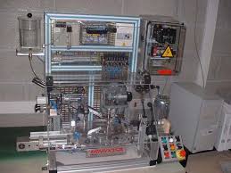
 Dossier technique MINIDOSA
* Grafcet du point de vue partie opérative de la tâche de transfert……… page 18. * Grafcet du point de vue partie opérative de la tâche de remplissage… page
 1.1. Partie Opérative 1.2. Partie Commande
Un GRAFCET est un graphe (diagramme) constitué par une alternance d'étapes et de transitions reliées par des arcs orientés. 3.1. Eléments de base. Ce sont :.
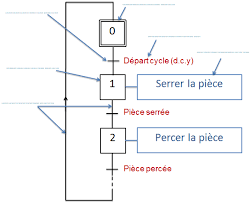 Leçon n°2 : PC PO
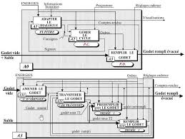
On s'intéresse à la matière d'œuvre. 2- GRAFCET de point de vue de la partie opérative. Il décrit la succession des tâches d'un système
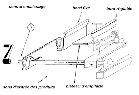 DOSSIER TECHNIQUE DE LENCAISSEUSE SEMI
8 GRAFCETS. 8-1 Grafcet du point de vue partie opérative. 8-2 Grafcet d'initialisation. 8-3 Grafcet de production normale du point de vue partie commande. 8-4
 Grafcets point de vue de la partie opérative Grafcet de sécurité GS
Grafcets point de vue de la partie opérative Grafcet de sécurité GS. 1. 2 validation tâche par grafcet GC. > index. 47. 48 absence forèt. Sortir vérin de.
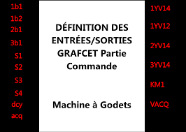 GRAFCET Graphe Fonctionnel de Commande Etapes Transitions
le point de vue partie opérative. Partant des TˆACHES le concepteur choisit les actionneurs et les capteurs. On va créer un GRAFCET d'un POINT DE VUE PARTIE
 C1 – INTRODUCTION AU GRAFCET
Grafcet PARTIE OPERATIVE. Page 20. 20. PARTIE. COMMANDE. Traiter les informations. Ordres. Matière d'œuvre (MO). Godet vide sable. Comptes- rendus. Evénement.
 Les différents points de vue dun grafcet
R le Grafcet du point de vue « partie opérative » indique le fonctionnement des actionneurs. R le Grafcet du point de vue « partie commande » indique le
 Les points de vue du grafcet
Grafcet point de vue système. Grafcet point de vue. Partie Opérative (PO). Grafcet point de vue. Partie Commande (PC). Grafcet codé automate. Equations
 LE GRAFCET POINT DE VUE PARTIE OPERATIVE
Le graphe de coordination des tâches est la représentation graphique de l'ordonnancement séquentiel ( organisation dans le temps ) des tâches du système. Il.
 LE GRAFCET POINT DE VUE PARTIE OPERATIVE
Le graphe de coordination des tâches est la représentation graphique de l'ordonnancement séquentiel ( organisation dans le temps ) des tâches du système. Il.
 Les points de vue du grafcet
%Q0.2.2. Grafcet point de vue système. Grafcet point de vue. Partie Opérative (PO). Grafcet point de vue. Partie Commande (PC). Grafcet codé automate.
 GRAFCET and Petri Nets Outline Introduction GRAFCET
GRAFCET. ? Graphe de Commande Etape Transition (Step Transition Control. Graph). ? 2 levels PROCEDURES EN DEFAILLANCE DE LA PARTIE OPERATIVE.
 Les différents points de vue dun grafcet
à l'infinitif décrivant l'action que doit réaliser le système. R dans le Grafcet du point de vue « partie opérative » les actions sont formulées en indiquant
 Grafcet Designer v.2.0
power failure or surges fire
 Le GRAFCET.pdf
destinés au traitement des informations émises par les organes de commande de la PR et capteurs de la PO. PARTIE. COMMANDE. (PC). PARTIE. OPERATIVE. (PO).
 PROSIM in the Cloud: Remote Automation Training Platform with
16-Mar-2022 third parties e.g.
 SYSTEMES SEQUENTIELS : LE GRAFCET
vue partie opérative ou encore la description du fonctionnement attendu d'une partie commande identifiée. 2. L'outil graphique. Le modèle GRAFCET : il
 Le GRAFCET (GRAphe Fonctionnel de Commande Étape et
Stade 2 : Choix des procédés de la production adaptés et détermination de la partie opérative. (actionneurs capteurs et éléments de dialogue pour l'opérateur).
 LE GRAFCET ou une introduction aux Systèmes à Evénements
process à contrôler : machine outil. Partie opérative de la PC compteurs
 [PDF] LE GRAFCET POINT DE VUE PARTIE OPERATIVE
Le GRAFCET permet de représenter par affinement successifs le comportement de la partie commande d'un S A P selon les souhaits du concepteur Pour cela après le
 [PDF] Ch III – Systèmes à logique séquentielle – Le GRAFCET – p1
La situation initiale du grafcet caractérise le comportement initial de la partie commande vis-à-vis de sa partie opérative Elle correspond aux étapes actives
 [PDF] Le GRAFCET - Robert cireddu
La Partie Opérative (PO) qui opère sur la matière d'œuvre et le produit Elle regroupe : - les effecteurs : dispositifs terminaux qui agissent directement
 [PDF] grafcet-resume-de-courspdf - AlloSchool
Description du comportement de la partie opérative par un grafcet selon le point de vue de la Partie Opérative (PO) (niveau 1) Stade 3 : Choix d'une partie
 [PDF] Les points de vue du grafcet
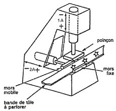
Les points de vue du grafcet Système : poinçonneuse Grafcet point de vue système Grafcet point de vue Partie Opérative (PO) Grafcet point de vue
 [PDF] le grafcet diagramme fonctionnel des automatismes sequentiels
Dès la conception le système à construire doit être décomposé en une partie opérative et une partie commande Cette structure permet un dialogue profi-
 [PDF] A GRAFCET règles et éléments - Sciences Industrielles en CPGE
Dans le cadre d'un système automatique le cahier des charges doit : • décrire le comportement de la partie opérative • préciser les différents modes de
 [PDF] Le Grafcetpdf - Cours et sujets BTS MAI BTS CRSA
Le grafcet décrit les interactions entre la partie opérative (PO) et la partie commande (PC) d'un système isolé Cette première frontière d'isolement permet de
 [PDF] Les différents points de vue dun grafcet - Gecifnet
R le point de vue « partie opérative » R le point de vue « partie commande » II – 1 – Le point de vue système Le GRAFCET selon le point de vue système
 [PDF] 1 GRAFCET : notions de base - D DUBOIS ESTIT
Le GRAFCET (GRAphe de Commande Etapes Transitions) est un diagramme fonctionnel dont le but est de décrire graphiquement suivant un cahier des charges
Grafcet Designer v.2.0
Reference Manual
April 2014
TecAtlant
Le Fort bloqué
27 Allée des Macareux
56270 Ploemeur
FRANCE
Tél. : +33 (0)9 80 32 79 40
©TecAtlant 1 Grafcet Designer v.2.0 - Reference ManualApril 2014 Edition
Warranty Limitation
The media on which you receive TecAtlant software are warranted not to fail to execute programminginstructions, due to defects in materials and workmanship, for a period of 90 days from the date of shipment, as
evidenced by receipts or other documentation. TecAtlant will, at this option, repair or replace software media
that do not execute programming instructions if TecAtlant receives notice of such defects during the warranty
period. TecAtlant does not warrant that the operation of the software shall be uninterrupted of error free.
A Return Material Authorization (RMA) number must be obtained from the factory and clearly marked on the
outside of the package before any equipment will be accepted for warranty work. TecAtlant will pay the
shipping costs of returning to the owner parts which are covered by warranty.TecAtlant believes that the information in this document is accurate. The document has been carefully reviewed
for technical accuracy. In the event that technical or typographical error exists. TecAtlant reserves the rights to
make changes to subsequent editions of this document without prior notice to holders of this edition. The reader
should consult TecAtlant if errors are suspected. In no event shall TecAtlant be liable for any damages arising
out of or related to this document or the information contained in it. E XCEPT AS SPECIFIED HEREIN, TECATLANT MAKES NO WARRANTIES, EXPRESS OR IMPLIED, AND SPECIFICALLY DISCLAIM ANY WARRANTY OF MERCHANTABILITY OR FITNESS FOR A PARTICULAR PURPOSE . COSTUMER'S RIGHT TO RECOVER DAMAGES CAUSED BY FAULT OR NEGLIGENCE ON THE PART OFTECATLANT SHALL BE LIMITED TO
THE AMOUNT THERETOFORE PAID BY THE COSTUMER
. TECATLANT WILL NOT BE LIABLE FOR DAMAGES RESULTINGFROM LOSS OF DATA
, PROFITS, USE OF PRODUCT, OR INCIDENTAL OF CONSEQUENTIAL DAMAGES, EVENT IFADVISED OF THE POSSIBILITY THEREOF
. This limitation of the liability of TecAtlant will apply regardless of theform of action, whether in contract or tort, including negligence. Any action against TecAtlant must be brought
within one year after the cause of action accrues. TecAtlant shall not be liable for any delay in performance due
to causes beyond its reasonable control. The warranty provided herein does not cover damages, defects,
malfunctions, or service failures caused by owner's failure to follow TecAtlant installation, operation, or
maintenance instructions; owner's modification of the product; owner's abuse, misuse, or negligent acts; and
power failure or surges, fire, flood, accident, actions of third parties, or other events outside reasonable control.
Copyright
Grafcet Designer® software and its handbook reproduction are all rights reserved. Under the copyright laws, this
publication and the software may not be reproduced or transmitted (except for a backup copy of the software), in
any forms, electronic or mechanical, including photocopying, recording, storing in an information retrieval
system, or translating, in whole or in part, without the prior written consent of TecAtlant Corporation.
Trademarks
LabVIEW® is a National Instruments Corporation trademark. Macintosh® is an Apple Computer Inc trademark. Windows® is a Microsoft trademark.Product and company names mentioned herein are trademarks or trade names of their respective companies.
©TecAtlant 2 Grafcet Designer v.2.0 - Reference ManualApril 2014 Edition
Warning regarding use of TecAtlant products
(1) TECATLANT PRODUCTS ARE NOT DESIGNED WITH COMPONENTS AND ARE TESTING FOR A LEVEL OF RELIABILITY SUITABLE FOR USE IN OR IN CONNECTION WITH SURGICAL IMPLANTS OR AS CRITICAL COMPONENTS IN ANY LIFE SUPPORT SYSTEMS WHICH FAILURE TO PERFORM CAN BE REASONABLY BEEXPECTED TO CAUSE SIGNIFICANT INJURY TO A HUMAN
(2) I N ANY APPLICATION, INCLUDING THE ABOVE, RELIABILITY OF OPERATION OF THE SOFTWARE PRODUCTSCAN BE IMPAIRED BY ADVERSE FACTORS
, INCLUDING BUT NOT LIMITED TO FLUCTUATIONS INELECTRICAL POWER SUPPLY
. HARDWARE MALFUNCTIONS, COMPUTER OPERATING SYSTEM SOFTWAREFITNESS
, FITNESS OF COMPILERS AND DEVELOPMENT SOFTWARE USED TO DEVELOP AN APPLICATION,INSTALLATION ERRORS
, SOFTWARE AND HARDWARE COMPATIBILITY PROBLEMS, MALFUNCTIONS OR FAILURES OF ELECTRONIC MONITORING OR CONTROL DEVICES , TRANSIENT FAILURES OF ELECTRONICSYSTEM
(HARDWARE AND/OR SOFTWARE), UNANTICIPATED USES OR MISUSE, OR ERROR ON PART OF THEUSER OR APPLICATIONS DESIGNER
(ADVERSE FACTORS SUCH AS THESE ARE HEREAFTER COLLECTIVELYTERMED
"SYSTEM FAILURES"). ANY APPLICATION WHERE A SYSTEM FAILURE WOULD CREATE E RISK OFHARM TO PROPERTY OR PERSONS
(INCLUDING THE RISK OF BODILY INJURY AND DEATH) SHOULD NOT BE RELIANT SOLELY UPON ONE FORM OF ELECTRONIC SYSTEM DUE TO THE RISK OF SYSTEM FAILURE TOAVOID DAMAGE
, INJURY, OR DEATH, THE USER OR APPLICATION DESIGNER MUST TAKE REASONABLYPRUDENCE STEP TO PROTECT AGAINST SYSTEM FAILURES
, INCLUDING BUT NOT LIMITED TO BACK-UP ORSHUT DOWN MECHANISMS
. BECAUSE EACH END-USER SYSTEM IS CUSTOMIZED AND DIFFERS FROM TECATLANT'S TESTING PLATFORMS AND BECAUSE A USER OR APPLICATION DESIGNER MAY USE TECATLANT PRODUCTS WITH OTHER PRODUCTS IN MANNER NOT EVALUATED OR CONTEMPLATED BY TECATLANT, THE USER OR APPLICATION DESIGNER IS ULTIMATELY RESPONSIBLE FOR VERIFYING ANDVALIDATING THE SUITABILITY OF
TECATLANT PRODUCTS WHENEVER TECATLANT PRODUCTS AREINCORPORATED IN A SYSTEM OR APPLICATION
, INCLUDING, WITHOUT LIMITATION, THE APPROPRIATEDESIGN
, PROCESS AND SAFETY LEVEL OF SUCH SYSTEM OR APPLICATION. ©TecAtlant 3 Grafcet Designer v.2.0 - Reference ManualEdition de April 2014
Table of contents
ABOUT THIS MANUAL..................................................................................................................................... 4
CONVENTIONS..................................................................................................................................................... 4
CONTACTS WITH CUSTOMERS.............................................................................................................................. 4
CHAPTER 1. GRAFCET DESIGNER INSTALL............................................................................................5
MATERIAL REQUIREMENTS................................................................................................................................. 5
SOFTWARE REQUIREMENTS................................................................................................................................. 5
GRAFCET DESIGNER INSTALL.............................................................................................................................. 5
CHAPTER 2. THE GRAFCET (OR SFC)......................................................................................................... 6
CONSTRUCTION RULES OF A GRAFCET................................................................................................................. 6
Steps................................................................................................................................................................ 6
Transitions...................................................................................................................................................... 6
Directed arcs.................................................................................................................................................. 7
Convergences and divergences....................................................................................................................... 7
RULES OF EVOLUTION OF A GRAFCET.................................................................................................................. 7
CHAPTER 3. USING GRAFCET DESIGNER................................................................................................. 9
PRINCIPLE OF GRAFCET DESIGNER...................................................................................................................... 9
DEFINITION OF INPUTS/OUTPUTS....................................................................................................................... 11
Inputs............................................................................................................................................................ 11
Outputs ......................................................................................................................................................... 12
Customize inputs/outputs.............................................................................................................................. 13
EDITION OF A GRAFCET..................................................................................................................................... 14
The menu " Functions Grafcet Designer »................................................................................................... 14
Steps.............................................................................................................................................................. 15
The Conditional action editor wizard........................................................................................................... 18
The transition................................................................................................................................................ 19
The Conditional action editor wizard........................................................................................................... 22
Convergences and divergences..................................................................................................................... 23
Arrows upwards............................................................................................................................................ 23
Directed arcs................................................................................................................................................ 24
Syntactic analysis of grafcets........................................................................................................................ 25
Grafcets not related...................................................................................................................................... 26
Front panel of edited SFC VI........................................................................................................................ 26
CREATION OF THE APPLICATION........................................................................................................................ 27
Highlighting execution.................................................................................................................................. 28
LabVIEW Real Time..................................................................................................................................... 28
GRAFCET DESIGNER MENUS AND WINDOWS...................................................................................................... 29
Preferences windows.................................................................................................................................... 29
Examples....................................................................................................................................................... 30
The wizards................................................................................................................................................... 31
APPENDIX ......................................................................................................................................................... 32
CONTACTS WITH CUSTOMERS............................................................................................................................ 33
TECHNICAL SUPPORT FORM...............................................................................................................................34
DOCUMENTATION FORM.................................................................................................................................... 35
BIBLIOGRAPHICAL REFERENCES....................................................................................................................... 36
Reference books............................................................................................................................................ 36
Standards...................................................................................................................................................... 36
©TecAtlant 4 Grafcet Designer v.2.0 - Reference ManualEdition de April 2014
About this manual
The Grafcet Designer reference manual describes the user interface of the GrafcetDesigner library.
To benefit fully from it, it is preferable that you are familiarised with Windows and with the programming language LabVIEW.Conventions
The following convention appears in this manual:
» The symbol » leads you through nested menu items and dialog box options to a final action. The sequence File»Page Setup»Options directs you to pull down the File menu, select the Page Setup item, and select Options from the last dialog box. This icon denotes a note, which alerts you to important information. This icon denotes a caution, which advice you of precaution to take to avoid injury, data loss, or a system crash. Bold Bold text denotes items that you must select or click in the software, such as menu items and dialog box options. Bold text also denotes parameter names, controls and buttons on the front panel, dialog boxes, selection of dialog boxes, menu names, and palette names. Italic Italic text denotes variables, emphasis, a cross reference, or an introduction to a key concept. This font also denotes text that is a placeholder for a word or value that you must supply. Bold italic Bold and italic text denotes a note, an advice or a warning.Contacts with customers
You will find forms of technical support and informative at the end of this manual, in the appendix "Contact with customers". Thanks to complete this forms and to return it indicating your comments and notes on this product and its handbook. You can also description which you will develop with this product to obtain more information and to help you to solve possible problems which you can encounter. ©TecAtlant 5 Grafcet Designer v.2.0 - Reference ManualEdition de April 2014
Chapter 1.
Grafcet Designer Install
This part describes the requirements to use Grafcet Designer and its installation procedure.Material Requirements
Grafcet Designer, as LabVIEW, is a multi-platform product. One version of Grafcet Designer is available on each platform that is supported byLabVIEW:
Software requirements
To install Grafcet Designer, you must previously install LabVIEW® on your system. The version 2.0 of Grafcet Designer is available for each version of LabVIEW® since the version 2010.Grafcet Designer Install
The install of Grafcet Designeris done automatically through its installer. You can download an autonom version of this installer or a VIPM package (needs VI PackaeManager).
©TecAtlant 6 Grafcet Designer v.2.0 - Reference ManualEdition de April 2014
Chapter 2.
The GRAFCET (or SFC)
The GRAFCET (Functional Graph of Control Step Transition) or SFC (Sequential Function Charts) is a formal model being used to specify and also to control reactive systems of the type "all or nothing" (Boolean inputs and outputs). An automated system of production (ASP) breaks up into two parts: the control part and the operative part. The operative part includes the process having to be controlled as well as the operator. The control part is intended to process the data coming from the operative part to control it. The following presentation does not claim to be a definition of the grafcet but just an introduction. Moreover, one will reveal there only the concepts of GRAFCET which were implemented in Grafcet Designer.Structure of a Grafcet and interpretation
Construction rules of a grafcet
A grafcet is graph which is composed of steps and transitions, connected between them by connections or directed arcs. Steps 1 3 A Step is represented by a square to which a unique number is associated. A Step can be initial (represented by a double square).A Step is either active or inactive.
The whole of active steps (called situation) entirely defines the state of the system. We specify for each step, the actions to be executed. These actions are executed only when the corresponding step is active. We can associate a condition to those actions, the action is then executed only if the step is active and the condition is performed.Transitions
A transition is represented by a horizontal line.
A transition represents a possibility of change of the comportment of the system. This change of comportment (the passage from oneChapter 2
The GRAFCET (or SFC)
©TecAtlant 7 Grafcet Designer v.2.0 - Reference Manual April 2014 Edition step to the following) corresponds to the crossing of a transition. A transition is validated when all previous steps are active. The logical proposal which conditions the transition calls the receptivity.Directed arcs
Each directed arcs links a step to a transition or a transition to a step: there is always strict alternation: step-transition. When this connection is connection is directed upwards, we show the direction by an arrow upwards.Convergences and divergences
When the directed arcs start from several steps (known as steps downstream) and arrive on the same transition or when directed start from the same transition and arrive on several steps (known as steps upstream) then these regrouping are represented by two horizontal parallel lines respectively called convergence and divergence "in and". When separation is in the direction from several transitions to a common step (respectively from a step to several transitions), we name them convergences (respectively divergence) "in or". Their representation is done by dividing the directed connections.Rules of evolution of a grafcet
The evolution of a grafcet is subject to five rules:Rule 1: Initial situation
The initial situation of a grafcet characterizes the initial behaviour of the control part with respect to the operative part, to the operator and/or to the external elements. It corresponds to the active steps at the beginning of operation: those steps are the initial steps.Rule 2: Crossing a transition
A transition is validated when all immediately preceding steps connected to this transition are active. The crossing of the transition occurs: when the transition is validated, AND when the receptivity associated with this transition is true.Rule 3: Evolution of activated steps
The crossing of a transition involves simultaneously the activation of all immediately following steps and the inactivation of all immediately preceding steps.Rule 4: Simultaneous evolution
Several simultaneously crossable transitions are simultaneously crossed. Rule 5: Simultaneous activation and inactivation If during operation same step is simultaneously activated and inactivated, it remains active.Chapter 2
The GRAFCET (or SFC)
©TecAtlant 8 Grafcet Designer v.2.0 - Reference ManualApril 2014 Edition
quotesdbs_dbs44.pdfusesText_44[PDF] inéquation du second degré ? deux inconnues
[PDF] représentation graphique d'un système d'équation
[PDF] lire la solution de chaque système sur le graphique
[PDF] résoudre graphiquement un système d'équation
[PDF] systeme d'equation resolution graphique
[PDF] mémoire scientifique
[PDF] parti ou partie
[PDF] ils font partie intégrante
[PDF] faire parti conjugaison
[PDF] faire partie synonyme
[PDF] faire partie larousse
[PDF] tirer partie
[PDF] prendre ? parti larousse
[PDF] faire partir conjugaison
