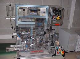
 Dossier technique MINIDOSA
* Grafcet du point de vue partie opérative de la tâche de transfert……… page 18. * Grafcet du point de vue partie opérative de la tâche de remplissage… page
 1.1. Partie Opérative 1.2. Partie Commande
Un GRAFCET est un graphe (diagramme) constitué par une alternance d'étapes et de transitions reliées par des arcs orientés. 3.1. Eléments de base. Ce sont :.
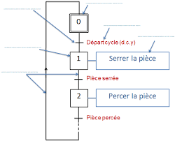 Leçon n°2 : PC PO
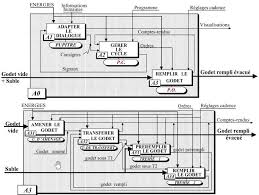
On s'intéresse à la matière d'œuvre. 2- GRAFCET de point de vue de la partie opérative. Il décrit la succession des tâches d'un système
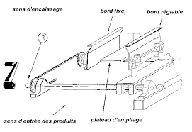 DOSSIER TECHNIQUE DE LENCAISSEUSE SEMI
8 GRAFCETS. 8-1 Grafcet du point de vue partie opérative. 8-2 Grafcet d'initialisation. 8-3 Grafcet de production normale du point de vue partie commande. 8-4
 Grafcets point de vue de la partie opérative Grafcet de sécurité GS
Grafcets point de vue de la partie opérative Grafcet de sécurité GS. 1. 2 validation tâche par grafcet GC. > index. 47. 48 absence forèt. Sortir vérin de.
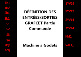 GRAFCET Graphe Fonctionnel de Commande Etapes Transitions
le point de vue partie opérative. Partant des TˆACHES le concepteur choisit les actionneurs et les capteurs. On va créer un GRAFCET d'un POINT DE VUE PARTIE
 C1 – INTRODUCTION AU GRAFCET
Grafcet PARTIE OPERATIVE. Page 20. 20. PARTIE. COMMANDE. Traiter les informations. Ordres. Matière d'œuvre (MO). Godet vide sable. Comptes- rendus. Evénement.
 Les différents points de vue dun grafcet
R le Grafcet du point de vue « partie opérative » indique le fonctionnement des actionneurs. R le Grafcet du point de vue « partie commande » indique le
 Les points de vue du grafcet
Grafcet point de vue système. Grafcet point de vue. Partie Opérative (PO). Grafcet point de vue. Partie Commande (PC). Grafcet codé automate. Equations
 LE GRAFCET POINT DE VUE PARTIE OPERATIVE
Le graphe de coordination des tâches est la représentation graphique de l'ordonnancement séquentiel ( organisation dans le temps ) des tâches du système. Il.
 LE GRAFCET POINT DE VUE PARTIE OPERATIVE
Le graphe de coordination des tâches est la représentation graphique de l'ordonnancement séquentiel ( organisation dans le temps ) des tâches du système. Il.
 Les points de vue du grafcet
%Q0.2.2. Grafcet point de vue système. Grafcet point de vue. Partie Opérative (PO). Grafcet point de vue. Partie Commande (PC). Grafcet codé automate.
 GRAFCET and Petri Nets Outline Introduction GRAFCET
GRAFCET. ? Graphe de Commande Etape Transition (Step Transition Control. Graph). ? 2 levels PROCEDURES EN DEFAILLANCE DE LA PARTIE OPERATIVE.
 Les différents points de vue dun grafcet
à l'infinitif décrivant l'action que doit réaliser le système. R dans le Grafcet du point de vue « partie opérative » les actions sont formulées en indiquant
 Grafcet Designer v.2.0
power failure or surges fire
 Le GRAFCET.pdf
destinés au traitement des informations émises par les organes de commande de la PR et capteurs de la PO. PARTIE. COMMANDE. (PC). PARTIE. OPERATIVE. (PO).
 PROSIM in the Cloud: Remote Automation Training Platform with
16-Mar-2022 third parties e.g.
 SYSTEMES SEQUENTIELS : LE GRAFCET
vue partie opérative ou encore la description du fonctionnement attendu d'une partie commande identifiée. 2. L'outil graphique. Le modèle GRAFCET : il
 Le GRAFCET (GRAphe Fonctionnel de Commande Étape et
Stade 2 : Choix des procédés de la production adaptés et détermination de la partie opérative. (actionneurs capteurs et éléments de dialogue pour l'opérateur).
 LE GRAFCET ou une introduction aux Systèmes à Evénements
process à contrôler : machine outil. Partie opérative de la PC compteurs
 [PDF] LE GRAFCET POINT DE VUE PARTIE OPERATIVE
Le GRAFCET permet de représenter par affinement successifs le comportement de la partie commande d'un S A P selon les souhaits du concepteur Pour cela après le
 [PDF] Ch III – Systèmes à logique séquentielle – Le GRAFCET – p1
La situation initiale du grafcet caractérise le comportement initial de la partie commande vis-à-vis de sa partie opérative Elle correspond aux étapes actives
 [PDF] Le GRAFCET - Robert cireddu
La Partie Opérative (PO) qui opère sur la matière d'œuvre et le produit Elle regroupe : - les effecteurs : dispositifs terminaux qui agissent directement
 [PDF] grafcet-resume-de-courspdf - AlloSchool
Description du comportement de la partie opérative par un grafcet selon le point de vue de la Partie Opérative (PO) (niveau 1) Stade 3 : Choix d'une partie
 [PDF] Les points de vue du grafcet
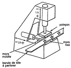
Les points de vue du grafcet Système : poinçonneuse Grafcet point de vue système Grafcet point de vue Partie Opérative (PO) Grafcet point de vue
 [PDF] le grafcet diagramme fonctionnel des automatismes sequentiels
Dès la conception le système à construire doit être décomposé en une partie opérative et une partie commande Cette structure permet un dialogue profi-
 [PDF] A GRAFCET règles et éléments - Sciences Industrielles en CPGE
Dans le cadre d'un système automatique le cahier des charges doit : • décrire le comportement de la partie opérative • préciser les différents modes de
 [PDF] Le Grafcetpdf - Cours et sujets BTS MAI BTS CRSA
Le grafcet décrit les interactions entre la partie opérative (PO) et la partie commande (PC) d'un système isolé Cette première frontière d'isolement permet de
 [PDF] Les différents points de vue dun grafcet - Gecifnet
R le point de vue « partie opérative » R le point de vue « partie commande » II – 1 – Le point de vue système Le GRAFCET selon le point de vue système
 [PDF] 1 GRAFCET : notions de base - D DUBOIS ESTIT
Le GRAFCET (GRAphe de Commande Etapes Transitions) est un diagramme fonctionnel dont le but est de décrire graphiquement suivant un cahier des charges
Neghina, M.; Craciunean, D.;
Stamatescu, G. PROSIM in the
Cloud: Remote Automation
Training Platform with Virtualized
Infrastructure.Appl. Sci.2022,12,
3038.https://doi.or g/
10.3390/app12063038
Academic Editor: Antonio
Fernández-Caballero
Received: 27 January 2022
Accepted: 14 March 2022
Published: 16 March 2022
Publisher"s Note:MDPI stays neutral
with regard to jurisdictional claims in published maps and institutional affil- iations.Copyright:© 2022 by the authors.
Licensee MDPI, Basel, Switzerland.
This article is an open access article
distributed under the terms and conditions of the Creative CommonsAttribution (CC BY) license (
https:// creativecommons.org/licenses/by/4.0/).
applied sciencesArticle
PROSIM in the Cloud: Remote Automation Training Platform with Virtualized InfrastructureSabin Rosioru
1,2, Viorel Mihai
1,2, Mihai Neghina
3, Daniel Craciunean
3and Grigore Stamatescu
2,*1Asti Automation, Calea Plevnei 139, 060011 Bucharest, Romania; sabin.rosioru@astiautomation.com (S.R.);
viorel.mihai@astiautomation.com (V.M.)2Department of Automation and Industrial Informatics, University Politehnica of Bucharest,
Splaiul Independentei 313, 060042 Bucharest, Romania3Department of Electrical Engineering and Computer Science, University "Lucian Blaga" of Sibiu,
Emil Cioran 4, 550025 Sibiu, Romania; mihai.neghina@ulbsibiu.ro (M.N.); daniel.craciunean@ulbsibiu.ro (D.C.) *Correspondence: grigore.stamatescu@upb.ro; Tel.: +40-723425323Abstract:
The need for high-availability, efficient, training solutions for industrial automation technol-ogy is driving the adoption of new tools, software and services supporting the Industry 4.0 paradigm.
Specific requirements include vendor agnostic and standards-based programming languages and availability of both physical input-output and industrial communication, while providing a rich and immersive experience through suitable human-machine interface components. The PROSIM platform represents an integrated embedded hardware-software system for programmable logic controller automation training which provides examples in increasing order of complexity, ranging from basic digital logic up to complex manufacturing simulations and process control. A fully software-based solution has been developed in order to complement the laboratory-based system as a training digital twin. We describe the design, implementation and evaluation of the platform as ported onto the HUBCAP collaborative sandboxing environment for virtualized operation. Integration of dedicated communication libraries for Open Platform Communications, Unified Architecture, with simulated programmable logic controllers such as PLCSIM and ARSim is also discussed for fully leveraging new features emerging from increased information and operational technology convergence witnessedin realistic, plant-level, environments. Qualitative and quantitative evaluation in comparison to the
physical system while leveraging the resources provided by the cloud environment is carried out.Keywords:
industrial automation; training; process simulations; OPC-UA; virtualization; cloud platform; Industry 4.01. Introduction Enabling remote automation technology training for higher education and continu- ing professional education requires suitable hardware-software platforms that leverage recent advances in cyberphysical systems and industrial internet of things. Specific topics include sensor technology, industrial communication, drive systems, programmable logic controllers and human-machine interfaces. Key design objectives are to enable easy knowl- edge transfer and practical expertise to the trainees, while balancing intuitive operations with the complexities that exist in a realistic plant or factory environment. Automation training is usually carried out in a dedicated, well-equipped laboratory that allows for physical implementation of the solution with failure simulations for increased realism. Recent public health challenges have accelerated the trend towards e-learning and virtual learning solutions, including for hands-on, resource-intensive fields such as industrial au- tomation technology. This situation, overlapping an already-existing underlying trend for digitalization of Industry 4.0 education, has led to hybrid or fully virtual training courses where the student can initially gain expertise on the automation of a continuous processsimulation followed by hands-on sessions in the laboratory. This represents, in some cases,Appl. Sci.2022,12, 3038.https://doi.or g/10.3390/app12063038https://www .mdpi.com/journal/applsci
Appl. Sci.2022,12, 30382 of 20significant time and cost benefits with added environmental advantages stemming from a
reduction in the need for national or international travel. Secondary benefits can also be highlighted from the perspective of educational institutions, which are able to limit capital investments in hardware and easily scale a software solution depending on the number of students and the training courses that they follow every year. The long-expected lifespan of hardware equipment in industrial automation systems also supports the importance and interest in high-level proper automation training solutions. The PROSIM process simulation automation training system has been initially con- ceived as a practical solution for programmable logic controller (PLC) training that com- bines the commercial automation hardware with custom software. The concept is vendor agnostic, allowing for PLC hardware from any manufacturer to be used as long as it com- plies with the required number and type of input-output channels. An early version of the system with firmware-based microcontroller-level simulation is described in [1]. The sys- tem contains a Siemens S7-300 family PLC training board, including a power supply, central processing unit (CPU), analog and digital input-output modules, and a demonstration panel connected through physical input-output signal to the PLC. The demonstration pan- els includes lamps, switches and potentiometers for the interaction with the programmed logic together with detachable masks and a selector switch that allows the selection of the programming task according to the studied documentation. The following PLC pro- gramming languages are supported according to the IEC 61131-3: ladder diagram (LAD), statement list (STL) and function block diagram (FBD). An upgraded version (ASID) is presented in [2] where the microcontroller-based solution is replaced by a general-use em- bedded industrial PC with suitable RS-485 and Modbus data-acquisition modules (DAQ). The user interface is developed using C# programming language using the Microsoft Visual Studio integrated development environment (IDE) and Expression Blend environments. A launcher application allows the selection of and switching between various process simulations whereas the documentation, such as control narratives and i-o lists required by the student for PLC-side control logic implementation, is embedded into the application using contextual menus. A customized example of process simulations running on the ASID version for energy system modelling is carried out by [3]. These include an auto- matic circuit recloser, a burner system control and microgrid energy management system simulations. One-to-one mapping between the electrical diagrams corresponding to the control scheme and the software implementation is performed. Faults can be simulated as well as parametrization of the time constants corresponding to the physical equipment characteristics for increased realism. The touch panel system allows intuitive interaction by the students and fast visual feedback of the process simulation state. Various modelling languages and tools can be used concurrently for systematic discrete (Grafcet, Petri Nets) or continuous control system design (feedback control using technical computing software such as MATLAB and Simulink). The solution is compatible with both proprietary and open-source solutions through standards-based communication and software libraries for Modbus implementation and additional simulation developments. Within a recent context of integrating new technologies and models into industrial automation training systems, this article emphasizes the following contributions: Design and implementation of a fully software-based, yet realistic, system for remote automation training using simulated process models, interfacing of input-output signals through IIoT-enabled Open Platform Communications-Unified Architecture (OPC-UA) communication and simulated commercial-grade PLC development envi- ronment (B&R ARsim); Integration of the proposed solution within the HUBCAP collaborative cloud sand- boxing environment and highlighting platform features and resource metrics. The main differentiation of this work in comparison with a considerable body of knowledgeconcernedwithe-learning, virtualanddistancelearningsolutionsforuniversity- grade and technical training in automation technology consists in the deep component-level integration which allows full replicability and porting of the implemented routines onceAppl. Sci.2022,12, 30383 of 20the physical hardware becomes available. Through the functionalities of the HUBCAP
cloud environment, inter-sandbox exchanges are possible, which opens up the possibility of extending the PROSIM solution with related models and tools published by compatible third parties, e.g., dynamic discretized plant models with suitable control narratives and io lists to be connected to the virtual PLC using the PROSIM launcher and software libraries. The rest of the article is structured as follows: Section 2 is dedicated to a r eviewof the state of the art that frames our contributions within the existing scientific and technological developments; Section 3 pr esentsa detailed perspective on the industrial pr ocesssimulator development and the components that enable a fully virtualized solution in the cloud;Section
4 intr oducesthe HUBCAP sandboxing envir onmentwith detailed technical aspects that support the deployment of the PROSIM applications in a virtual machine; Section 5 illustrates, in detail, implementation aspects for representative process simulations, indus- trial communication primitives and PLC application development along with the operation of the fully software-based solution in the sandboxing environment. Section 6 concludes the article together with lessons learned and future potential developments.2. State of the Art
With reference to the preliminary description of our system from the introduction, a parallel development using a similar concept for a web-based front-end e-learning ap- proach for various systems such as DC-motor and three-tank plant is presented in [4,5]. Detailed mathematical modelling for the plants is described together with their discretized implementation. The control design is initially validated in MATLAB and subsequently ported in a backed web application. The solution is readily accessible via the internet on end-user devices such as desktops, laptops and tablet PCs. Integration with the control hardware, namely a Siemens S7-1200 family PLC is carried out by means of an Ether- net data-acquisition hardware. TCP/IP communication allows the access to the coupler while physical signals such as analog and digital inputs and outputs are conveyed to the PLC system through wires. Control performance is illustrated comparatively between the simulation approach and the e-learning discretized plant model with physical hardware controller using typical metrics such as steady-state error, settling time and overshoot. Additionally, for the more complex three-tank model simulation an enhanced functionality is provided that allows local storage of the experiment files by the students on a dedicated server for evaluation and replicability purposes. Relevant related works in the field of (virtualized) e-learning and process simulations in real scenarios that also include hardware modules and components are discussed next, to establish the scientific context and relevance of our contributions. In [6], a web-based so- lution for student training is described, which revolves around a web application together with RESTful services for data and command exchanges. The system is applicable for discrete manufacturing processes such as flexible assembly lines with a modular software architecture. Validation with the real hardware manufacturing stations is achieved through a dedicated S1000 RTU gateway unit. The two versions, connected to the physical line and to the simulator via TCP/IP communication can be operated in parallel in order to compare the accuracy of the simulation and observe the real behavior of the system. Several consid- erations are discussed from the point of view of the students which enables safe, remote operation of laboratory installations. In [7], the interoperability between industrial-grade automation equipment and low-cost generic purpose hardware is discussed. The authors describe an application that enables PLC code-testing and SCADA application develop- ment for students on prototype plants using an Arduino microcontroller module as signal interface. State machines are used to describe the physical process based on which the control logic is subsequently implemented and tested. Modelling and design for AR/VR applications of industrial automation simulations is presented by [8]. The authors acknowl- edge the emergence of rich, immersive, multimedia technology with direct application in industrial process modelling for digital twin engineering. This in turn requires suitable training methodologies. The main contributions involve the addition of human-robot inter- action in the case of collaborative robots, a large set of tasks and a flexible design that allowsAppl. Sci.2022,12, 30384 of 20the decoupling of the simulator-supporting architecture from the simulation applications.
The framework defines modules and their integration through interfaces and associated UML models. A state manager module coordinates the concurrent and sequential oper- ation of various defined tasks and subtasks. Examples are provided in aircraft assembly, high-voltage cell and machinery tool operations. Enabling technologies include JSON for process definitions, C# for software implementation alongside the Unity3D engine for environment generation, visualization and interaction. Deployment is envisioned through a client-server architecture where the server runs the prespecified models and multiple clients can connect to it and visualize, operate and parametrize the simulation. The key role of OPC communication for linking up sensors, controllers and instrumentations is further emphasized by [9]. Several use cases with dual applicability in both R&D and educational activities are described for automation of energy systems, networked industrial laboratory and educational hardware-in-the-loop platforms. Standardized communica- tion buses enable integration between various field equipment and controllers through software implementation of the OPC server agents using dedicated environments such as WinCC flexible or NI OPC. Wider availability of OPC clients is observed in both Matlab and LabVIEW Datalogging and Supervisory Control modules. A key idea of the study is the reusable nature of the laboratory architecture with various technologies and for various practical applications that replicate and extend existing hardware platforms for learning and experimentation. In [10], the PLC is defined as a key smart service provider for Industry 4.0 production systems for supporting smart industrial control services (SICS). New concepts that emphasize the importance for automation and PLC training in the context of capacity building for higher education are detailed in [11]. A conceptual benchmark system is presented which integrates Eaton-Moeller software and hardware with suitable input-output modules and devices on a single physical board. The goal is to facilitate teaching of ladder diagram, function block diagram and GRAFCET diagrams. In this case, the system requires extension modules in order to be able to realistically simulate industry processes beyond the learning of the PLC program development tasks. A semivirtual simulation training platform based on PLC hardware is presented by [12]. The authors describe the connection of a previous-generation Siemens S7-200 PLC system via a serial RS232 to a host system HMI for enabling intuitive training. Several simulation applications have been developed and documented, including the program design, i/o list and external wiring diagram for traffic light control, knowledge competition and a material car. It is concluded that such a solution increases the student interest in the content taught and mitigates the limitations due to available hardware stands for process models in the laboratory. An educational perspective of using such automation simulators in online teachingisdiscussedin[13]. Thetrainingset-upincludesavirtualSiemensS7-1200PLCand TIA Portal software which is connected to a Factory I/O virtual environment for modelling the industrial processes from a mechatronics perspective. The authors emphasize the importance of detailed study guides and step-by-step instructions to support the students and trainees during remote teaching. An important observation is to focus on building associations between the rich graphical simulations and the expected behavior of the real physical system with added complexity and uncertainty. As an alternative, a low-cost solution that enables remote access to existing laboratory systems is discussed along with practical insights in [14]. The key elements that assure continuity of PLC training include a scheduling system, remote desktop access, a graphical user interface and a microcontroller board. The PLC unit controls two physical experiments in this case, a conveyor system and a sorting machine. Visual feedback of the functionality and validation of correct operation and/or malfunctions is collected through a webcam. The developed Arduino- based interface conveys the GUI commands from the student to actions on the physical platforms, which are also interfaced to the PLC. In such way remote operation of the plant simulation is achieved. An overarching framework that supports the integration of such disparate platforms and systems, currently addressing local needs for automation and PLC training is introduced in [15]. Various typical PLC training assignments are illustrated that can form a common content for a skills-based training curriculum.Appl. Sci.2022,12, 30385 of 20A separate but complementary field of study is dedicated to large-scale process simu-
lations in chemical engineering. In these scenarios, usually specialized, domain-specific software tools are coupled with more generic technical computing environments through well-defined communication primitives. The domain-specific tools run the complex process models and generate the simulated process data, which is transmitted to an application in the external computing environment to be interpreted and serve as decision support for control actions. One example is presented in [16] for the coupling between Aspen HYSYS and MATLAB over OPC communication. The value proposal is supported by the fact that chemical process automation involves significant life, economic and environmental risks such that enabling simulated control for the initial design and evaluation of certain risk patterns and malfunction scenarios can help reduce such risks in the engineering phase.3. PRO-CPS Approach for Industrial Process Simulator Virtualization
Three generations of the process simulator SIMED/ASID/PROSIM V+ are briefly introduced in this section to provide a perspective regarding the evolution of the system towards the current cloud-based implementation. The physical realizations of these systems are illustrated in chronological order in Figure 1 .(a) SIMED(b) ASID(c) PROSIM V+ Figure 1.Three generations of the process simulator for industrial automation. The earliest version of the concept is represented by the SIMED modular process simulator composed of a demonstration board and a PLC system. The demonstration board is a microcontroller-based embedded system that hardcodes the process logic of the supported process simulations (20) and provides the user a dedicated button to switch the number of the simulation in order to match the existing experiment. The user also has to fit a custom process diagram on the demonstration panel that matches the relevant LED indicator lamps and buttons that are used to physically monitor and interact with the active process simulation. A dense ribbon cable connects the demonstration panel to the PLC unit. In this generation, a Siemens S7-300 family CPU with appropriate input and output modules has been used. Development and implementation of the control logic is carried out using the STEP7 development software according to listed process control narratives and variable lists. The original version of the integrated training process simulation for industrial au- tomation, ASID (PROSIM T+), is a cyber-physical system by design and leverages the latest advances in embedded hardware and software for developing robust industrial automation training technology. It includes an industrial embedded PC with Intel i3/i5 cpu, 4 GB of RAM and fast SSD storage unit coupled to a high quality 15" touchscreen display. The data acquisition subsystem provides 6 AI/4 AO 0-10 V and 16 DI/DO 0-24 V channels as modules on Modbus TCP/IP-Ethernet and Modbus RTU-RS485 bus. Applications are de-Appl. Sci.2022,12, 30386 of 20veloped using the C# programming language in self-contained Virtual Studio IDE projects.
The software platform is based on the Microsoft Windows 10 IoT operating system while2D/3D process simulations can be developed in multiple frameworks, e.g., Unity [17],
Matlab [18], CIROS [19] and deployed on ASID. This generation also increases the number of available simulations to 32. As the OPC-UA protocol can also been supported under Linux-based systems, this can extend the applicability of the solution to a wider class of computing systems. PROSIM V+ unbundles the three core parts: control hardware, data acquisition in- terface and process model libraries software as customized solutions. The existing imple- mentation of the PROSIM V+ at the start of the project included 30+ process simulations in increasing order of complexity, as follows: logic basic functions, digital function modules, motor on/off, reversing contactor, star-delta connection, reversing star-delta connection, pendulum table, Dahlander circuit, motor with two separate windings, wound-rotor motor, conveyor belt system, reactive power compensator, heating control, running light, auto- matic filling system, tank system, fan control, traffic lights for road works, traffic lights, goods lift, coal grinder, embossing machine, collecting belt conveyor, conveyor-charging system, silo control, reactor, pump control, wastewater pump system, monitoring of three pumps, pump system-pressure, drinks machine, sequence control. With the newly devel- oped simulation, the total number of available process simulations has reached 40. A summary of the hardware, software and functional characteristics of the three generations: SIMED (2008), ASID (2016) and PROSIM V+ (2020), is highlighted in Table 1 With regard to the shortcomings of the previous versions that have driven the need for the current iteration of the process simulator, together with technology advances that enable new functionalities and features, these include: limitation of SIMED to firmware-based simulations (impossibility of easily uploading and extending the system via software updates) with physical process masks for interfacing with the process and lack of industrial communication; built-in touchscreen of the ASID generation that increases the cost, weight and frailness of the hardware equipment in a context where the student and professors should be enabled to use their existing devices and given a choice between a local desktop, tablet or web interface. The new improvements mitigate these shortcomings and provide a more versatile platform which, as a virtualized solution for automation training, offers increased flexibility, lower cost and ubiquitous access to the process simulations and the full PLC application development environment, supported through a wider range of hardware equipment and features. Table 1.Comparative summary of the process simulator characteristics.SIMED ASID PROSIM V+Hardware Platform
Microcontroller-based
embedded systemAll-in-one x86/x64Industrial PCEmbedded PC boardSoftware Platform
Custom firmware
with hard-coded simulationsC# .NET ApplicationsWindows 10 IoTC# .NET Applications
Windows 10 IoTUser Interface
Lamps, buttons, switches and
user-replaceable process synoptic diagram masksBuilt-in touchscreenWebTablet PC
SmartphoneCommunicationn/aModbus TCP/IP
Modbus RTUModbus TCP/IP
Modbus RTUControl UnitSiemens S7-300 Siemens S7-1200Siemens S7-1200 orB&R X20 family
We envision PROSIM as a family of products and services: stand-alone training unit with embedded software and on board analog/digital i/o (ASID), decoupled software solution running on any Windows platform and dedicated i/o (PROSIM V+) towardsAppl. Sci.2022,12, 30387 of 20the fully virtualized solution with OPC-UA data communication between the process
simulations and simulated PLCs (PROSIM Cloud, detailed in this article). On the services side, the provider and the end user can deliver specialized PLC programming courses to end-users and developers in the process industries and, for larger customers, develop customized process simulations according to their specific equipment/plant. The value proposition lays in the acceleration of knowledge and practical skills acquisition for stu- dents, technicians and automation engineers. The technology-agnostic PROSIM platform reduces the need to invest in provider-specific training solutions from the equipment man- ufacturer. The diversified range of process simulations, in increasing order of complexity from basic digital logic to discrete manufacturing and continuous plant models for the process industries, including a digital-twin model of a control engineering platform, assures step-by-step skills development. Advanced concepts such as mathematical plant modelling with PID control and industrial communication over OPC-UA middleware are exposed to the end user in a packaged form alongside realistic examples of industry processes. All the simulations are documented through the control narrative, functional description andquotesdbs_dbs44.pdfusesText_44[PDF] inéquation du second degré ? deux inconnues
[PDF] représentation graphique d'un système d'équation
[PDF] lire la solution de chaque système sur le graphique
[PDF] résoudre graphiquement un système d'équation
[PDF] systeme d'equation resolution graphique
[PDF] mémoire scientifique
[PDF] parti ou partie
[PDF] ils font partie intégrante
[PDF] faire parti conjugaison
[PDF] faire partie synonyme
[PDF] faire partie larousse
[PDF] tirer partie
[PDF] prendre ? parti larousse
[PDF] faire partir conjugaison
