 Practice Problems - Chapter 33 Alternating Current Circuits
0.34 A. Page 2. 2 CHAPTER 33. 20. An RLC series circuit has R = 100 ohms C = 25 µF
 QUESTION BANK WITH ANSWERS
Determine the power factor of a RLC series circuit with R=5ohm XL=8ohm and XC=12ohm. (JUNE
 ELECTRICAL CIRCUITS LECTURE NOTES B.TECH (I YEAR – II
Example Problems: 1) Find the Req for the circuit shown in below figure. fig(a). Solution: To get Req we combine resistors in series and in parallel. The 6 ohms
 AC Electrical Circuit Analysis - A Practical Approach James M. Fiore
Apr 22 2021 D: Answers to Selected Odd-Numbered Problems . . . . 408. E: Questions for Selected Odd Answers . . . . . 422. 9. Page 10. 1 Fundamentals. 1.0 ...
 BEE-402; UNIT-I MESH AND NODAL ANALYSIS of AC circuits
Assume o=10° radians per second. == Solution 2: Convert the circuit to the phasor domain. Solve the problem using circuit techniques (nodal analysis mesh ...
 0.1. Single Phase AC circuit - JNNCE ECE Manjunath
Problems on Three phase AC circuits. 0.4 Problems on Three phase AC circuits Calculate power power factor and current in the circuit. Solution: Z = E. I. =.
 ee301 – phasors complex numbers in ac and impedance
Sep 22 2016 Solving AC circuit problems is greatly simplified through the use of the phasor transform. ... Solution: Example: Given: I1 = 20 sin (ω t) mA. I2 ...
 ELECTRICAL CIRCUIT ANALYSIS Lecture Notes Prepared By S
A.C TRANSIENT ANALYSIS: Transient response of R-L R-C
 DC NETWORK THEOREMS
This method which is particularly well-suited to coupled circuit solutions employs a system of ** Or impedance in the case of a.c. circuits. *. After the ...
 Ch31-AC Circuits.pdf
Alternating Current Circuits. • Alternating Current - AC Circuits: Resistor; Inductor; Capacitor ... RLC Circuit - Solution via Complex Numbers.
 BASIC ELECTRICAL ENGINEERING
In order to analyze AC circuit it is necessary to represent multi-dimensional quantities. In Problem: Find impedance Zin of below circuit. Solution: ...
 SINGLE PHASE AC CIRCUITS
Phasor Algebra for a pure resistive circuit. Problem 2. An ac circuit consists of a pure resistance of 10 and is connected to an ac supply of 230 V 50 Hz.
 ELECTRICAL CIRCUITS LECTURE NOTES B.TECH (I YEAR – II
Example Problems: 1) Find the Req for the circuit shown in below figure. fig(a). Solution: To get Req we combine resistors in series and in parallel.
 CBSE NCERT Solutions for Class 12 Physics Chapter 7
(b) The rms value of current in an ac circuit is 10 A. What is the peak current? Solution: (a). Given. Peak voltage
 Practice Problems - Chapter 33 Alternating Current Circuits
0.34 A. Page 2. 2 CHAPTER 33. 20. An RLC series circuit has R = 100 ohms C = 25 µF
 Series and parallel AC circuits This worksheet and all related files
A student measures voltage drops in an AC circuit using three voltmeters and arrives on this problem you realize that neither of the answers proposed.
 A-C Circuit Analysis - Alexander Schure.pdf
A-C CIRCUIT. ANALYSIS publication carefully selected problems afford the reader more profitable in- ... Solution. f = 1/t = l;.0025 = 400 cycles.
 Ver 3537 E1.1 Analysis of Circuits (2014) E1.1 Circuit Analysis
E1.1 Circuit Analysis. Problem Sheet 2 - Solutions. Note: In many of the solutions below I have written the voltage at node X as the variable X instead of.
 AC Electrical Circuit Analysis - A Practical Approach James M. Fiore
22?/04?/2021 This AC Electrical Circuit Analysis by James M. Fiore is copyrighted under the terms of ... D: Answers to Selected Odd-Numbered Problems.
Chapter 31
Alternating Current
Circuits
MFMcGraw-PHY 2426 Chap31-AC Circuits-Revised: 6/24/2012 2 Alternating Current Circuits•Alternating Current - GeneratorWave Nomenclature & RMS
AC Circuits: Resistor; Inductor; Capacitor
Transformers - not the movie
LC and RLC Circuits - No generator
Driven RLC Circuits - Series
Impedance and Power
RC and RL Circuits - Low & High Frequency
RLC Circuit - Solution via Complex Numbers
RLC Circuit - Example
Resonance
MFMcGraw-PHY 2426 Chap31-AC Circuits-Revised: 6/24/2012 3Generators
By turning the coils in the magnetic field an emf is generated in the coils thus turning mechanical energy into alternating (AC) power. MFMcGraw-PHY 2426 Chap31-AC Circuits-Revised: 6/24/2012 4Generators
Rotating the Coil in a Magnetic Field Generates an Emf •Examples: Gasoline generatorManually turning the crank
Hydroelectric power
MFMcGraw-PHY 2426 Chap31-AC Circuits-Revised: 6/24/2012 5Generators
m m m peak peakφ= NBAcosθ θ=ωt
φ= NBAcosωt
d= - φ = NBAωsinωtdt = sinωt; = NBAωε MFMcGraw-PHY 2426 Chap31-AC Circuits-Revised: 6/24/2012 6Wave Nomenclature and RMSValues
MFMcGraw-PHY 2426 Chap31-AC Circuits-Revised: 6/24/2012 7Wave Nomenclature
A peak-peak = Ap-p = 2Apeak = 2Ap; Ap = Ap-p /2 MFMcGraw-PHY 2426 Chap31-AC Circuits-Revised: 6/24/2012 8 ? ?? ?? ?? ?? ?sinx = A ωt -cos{ } sin tx = A 2π-cos T( )( )π2π π2 2
x = A sin ωt - x = A sinωt cos - sin cosωt x = A sinωt (0)-(1)cosωt x = -AcosωtThe minus sign means that the
phase is shifted to the right.A plus sign indicated the phase
is shifted to the leftShifting Trig Functions
MFMcGraw-PHY 2426 Chap31-AC Circuits-Revised: 6/24/2012 9Shifting Trig Functions
t - = 02 t =2π1 1 Tt = ; =2ω ω 2πT Tt = =2 2π
4πsin ωt - = 02
Shifted Trig Functions
-1.50-1.00-0.500.000.501.001.50 -3.00 -2.00 -1.00 0.00 1.00 2.00 3.00 Time sin(ωt)
sin(ωt-δ)
MFMcGraw-PHY 2426 Chap31-AC Circuits-Revised: 6/24/2012 10Root Mean Squared
Procedure
•Square it (make the negative values positive)Take the average (mean)
Take the square root (undo the squaring operation)The root mean squared (rms) method of averaging is used when a variable will average to zero but its effect will not average to zero.
MFMcGraw-PHY 2426 Chap31-AC Circuits-Revised: 6/24/2012 11Sine Functions
-1.5-1.0-0.50.00.51.01.50.0 1.0 2.0 3.0 4.0 5.0 6.0 7.0
Angle (Radians)
SIN(Theta)SIN2(Theta)RMS Value
Root Mean Squared Average
MFMcGraw-PHY 2426 Chap31-AC Circuits-Revised: 6/24/2012 12Average of a Periodic Function
∫ ∫ ∫T avg p o cos(ωT)T
ωT p p avg p o 0 cos(0) p avg1V =V = V(t)dt; V(t)=V sinωtT
V V1V = V sin
ωtdt = sinxdx = - d(cosx)
T ωTωT
VV = - (1-1)= 0ωT
MFMcGraw-PHY 2426 Chap31-AC Circuits-Revised: 6/24/2012 13Root Mean Squared( )
∫T 2 2 2 pavgo 2 2 2 T p p p 2 2 avgo 2 p 2 avg 2RMS p pavg1V = V = V (t)dt; V(t)=V sinωtT
V V VV = sin ωtdt = π = T ωT 2 VV =2 1V V = V = 0.707V2
MFMcGraw-PHY 2426 Chap31-AC Circuits-Revised: 6/24/2012 14Root Mean Squared
2RMS p pavg
1 V V = V = 0.707V2
Root Square
Mean The RMS voltage (VRMS )is the DC voltage that has the same effect as the actual AC voltage. MFMcGraw-PHY 2426 Chap31-AC Circuits-Revised: 6/24/2012 15RMS Power
The average AC power is the product of the DC equivalent voltage and current. avg p p p pRMS RMS
avg RMS RMS avg RMS RMS1P = V I2
V Isince V = and I =2 2
1P = 2 V 2 I2
P =V I
MFMcGraw-PHY 2426 Chap31-AC Circuits-Revised: 6/24/2012 16Resistor in an AC Circuit MFMcGraw-PHY 2426 Chap31-AC Circuits-Revised: 6/24/2012 17Resistor in an AC Circuit
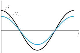
For the case of a resistor in an AC circuit the VR across the resistor is in phase with the current I through the resistor. In phase means that both waveforms peak at the same time. MFMcGraw-PHY 2426 Chap31-AC Circuits-Revised: 6/24/2012 18Resistor in an AC Circuit
22p 2 2 p
P(t)= I (t)R = I cosωt R
P(t)= I RcosωtThe instantaneous power is a function of time. However, the average power per cycle is of more interest. MFMcGraw-PHY 2426 Chap31-AC Circuits-Revised: 6/24/2012 19Inductors in an AC Circuit MFMcGraw-PHY 2426 Chap31-AC Circuits-Revised: 6/24/2012 20Coils & Caps in an AC Circuit
MFMcGraw-PHY 2426 Chap31-AC Circuits-Revised: 6/24/2012 21Inductors in an AC Circuit
For the case of an inductor in an
AC circuit the VL across the
inductor is 900 ahead of the current
I through the inductor.
MFMcGraw-PHY 2426 Chap31-AC Circuits-Revised: 6/24/2012 22Inductors in an AC Circuit
L peak
pL peak L peak
p LLVπI = I sinωt = cosωt -2ωL
V VI = =ωL X
X =ωL
XL is the inductive reactance
MFMcGraw-PHY 2426 Chap31-AC Circuits-Revised: 6/24/2012 23Average Power - Inductors( )( )
L L peak p
L peak p
T avg L peak p 0 TL peak p
avg 0 TL peak p
avg 0P(t)=V I = V cosωt I sinωt
P(t)=V I cosωt sinωt
1P = V I cosωt sinωtdtT
V IP = cosωt sinωtdtT
V IP = sin2ωtdt = 02TInductors don't dissipate energy, they store energy. MFMcGraw-PHY 2426 Chap31-AC Circuits-Revised: 6/24/2012 24Average Power - Inductors
Inductors don't dissipate energy, they
store energy.The voltage and the current are out of
phase by 90o.As we saw with Work, energy
changed only when a portion of the force was in the direction of the displacement.In electrical circuits energy is
dissipated only if a portion of the voltage is in phase with the current. MFMcGraw-PHY 2426 Chap31-AC Circuits-Revised: 6/24/2012 25Capacitors in an AC Circuit MFMcGraw-PHY 2426 Chap31-AC Circuits-Revised: 6/24/2012 26Capacitors in an AC Circuit
C p C p
C C p p
p p p pV = cosωt =V cosωtQ =V C =V Ccosωt = Q cosωt
dQI = = -ωQ sinωt = -I sinωtdtI = -ωQ sinωt = I cosωt +2
For the case of a capacitor in an
AC circuit the VC across the
capacitor is 900 behind the current
I on the capacitor.
MFMcGraw-PHY 2426 Chap31-AC Circuits-Revised: 6/24/2012 27Capacitors in an AC Circuit
Cp Cp p p Cp CCV VI =ωQ =ωCV = =1XωC
1X =ωC
XC is the capacitive reactance.
MFMcGraw-PHY 2426 Chap31-AC Circuits-Revised: 6/24/2012 28Electrical Transformers MFMcGraw-PHY 2426 Chap31-AC Circuits-Revised: 6/24/2012 29Electrical Transformers
MFMcGraw-PHY 2426 Chap31-AC Circuits-Revised: 6/24/2012 30Electrical Transformers
MFMcGraw-PHY 2426 Chap31-AC Circuits-Revised: 6/24/2012 31 MFMcGraw-PHY 2426 Chap31-AC Circuits-Revised: 6/24/2012 32Electrical Transformers
MFMcGraw-PHY 2426 Chap31-AC Circuits-Revised: 6/24/2012 33Electrical Transformers
Both coils see the same magnetic flux and the cross sectional areas are the same 00 1 1 0 2 2
1 1 2 2
1 2 1 2 2 1 2 2 1 2 1 1B = μnI
μn I =μn I
n I = n I nI = InNI n NL= = =NI n N
L MFMcGraw-PHY 2426 Chap31-AC Circuits-Revised: 6/24/2012 34Electrical Transformers
Conservation of Energy
Primary Power = Secondary Power
in 1 out 2 out 1 2 in 2 1 2 out in1V I =V I
VI N= =V I N
NV = VN
Induced voltage/loop
More loops => more voltage
Voltage steps up but the current
steps down. MFMcGraw-PHY 2426 Chap31-AC Circuits-Revised: 6/24/2012 35LC and RLC Circuits Without aGenerator
MFMcGraw-PHY 2426 Chap31-AC Circuits-Revised: 6/24/2012 36LC Circuit - No Generator
To start this circuit some energy must be placed in it since there is no battery to drive the circuit. We will do that by placing a charge on the capacitor Since there is no resistor in the circuit and the resistance of the coil is assumed to be zero there will not be any losses. MFMcGraw-PHY 2426 Chap31-AC Circuits-Revised: 6/24/2012 37LC Circuit - No Generator
Apply Kirchhoff's rule
2 2 2 2RdI QL + = 0dt C
dQSince I =dt d Q QL + = 0dt C d Q 1= - Qdt LC1ω=LC
This is the harmonic
oscillator equation MFMcGraw-PHY 2426 Chap31-AC Circuits-Revised: 6/24/2012 38LC Circuit - No Generator
p p pQ(t)= Q cos
ωt dQI(t)= = -ωQ sinωtdtπ
I(t)= -
ωQ cos
ωt +2
The circuit will oscillate at the frequency
ωR. Energy will flow back and forth
from the capacitor (electric energy) to the inductor (magnetic energy). MFMcGraw-PHY 2426 Chap31-AC Circuits-Revised: 6/24/2012 39RLC Circuit - No Generator
Like the LC circuit some energy must initially be placed in this circuit since there is no battery to drive the circuit. Again we will do this by placing a charge on the capacitor Since there is a resistor in the circuit now there will be losses as the energy passes through the resistor. MFMcGraw-PHY 2426 Chap31-AC Circuits-Revised: 6/24/2012 40RLC Circuit - No Generator
Apply Kirchhoff's rule
22dI Q dQL + IR+ = 0 ; I =dt C dt
d Q dQ 1L + R + Q = 0dt dt C "ma" termDamping term - friction
Restoring force "kx"
quotesdbs_dbs7.pdfusesText_13[PDF] ac frequency us
[PDF] ac tonnage calculation formula
[PDF] ac unit calculator
[PDF] ac2o dmap mechanism
[PDF] aca american cycling association
[PDF] aca certification accounting
[PDF] aca certification apple
[PDF] aca certification corrections
[PDF] aca certification cost
[PDF] aca certification courses
[PDF] aca certification exam
[PDF] aca certification phlebotomy
[PDF] aca code of ethics
[PDF] aca code of ethics pdf

